Building concrete compressive strength detection device

A compressive strength and detection device technology, applied in the direction of measuring devices, strength characteristics, test material hardness, etc., can solve the problems of lower detection accuracy, detection inconvenience, detection data deviation, etc., to achieve increased workload, easy operation, The effect of simple structure

Inactive Publication Date: 2020-11-03
刘玉荣
View PDF1 Cites 0 Cited by
  • Summary
  • Abstract
  • Description
  • Claims
  • Application Information

AI Technical Summary

Problems solved by technology

[0005] In order to make up for the deficiencies of the existing technology and solve the existing problems in the prior art, the hammer is used manually and pressed vertically to the surface of the building concrete to be tested. However, there are many deficiencies in the process. The detection brings inconvenience and also reduces the accuracy of the detection. First: manual operation is difficult to ensure that the rebound hammer and the concrete surface are in a completely vertical state, especially when pressing manually, the shaking of the hand will make the rebound hammer The angle between the surface of the concrete and the surface of the concrete presents a large change, but the change is difficult to be noticed by the operator, which leads to a large deviation of the detection data. Second: When detecting a concrete plane that is not completely horizontal or not completely vertical When the rebound hammer needs to be tested perpendicular to the concrete plane, the rebound hammer will also be in a non-horizontal or vertical state when it works in this case. Different, and then there will be deviations in the detected data. There will be a special conversion table here, but it is difficult to accurately detect the inclination angle of the concrete surface with conventional detection equipment, which brings great inconvenience to the detection. The present invention proposes a construction concrete Compressive strength testing device

Method used


Image

  • Building concrete compressive strength detection device
  • Building concrete compressive strength detection device
  • Building concrete compressive strength detection device

Examples


Embodiment Construction

[0025] In order to make the technical means, creative features, goals and effects achieved by the present invention easy to understand, the present invention will be further described below in conjunction with specific embodiments.

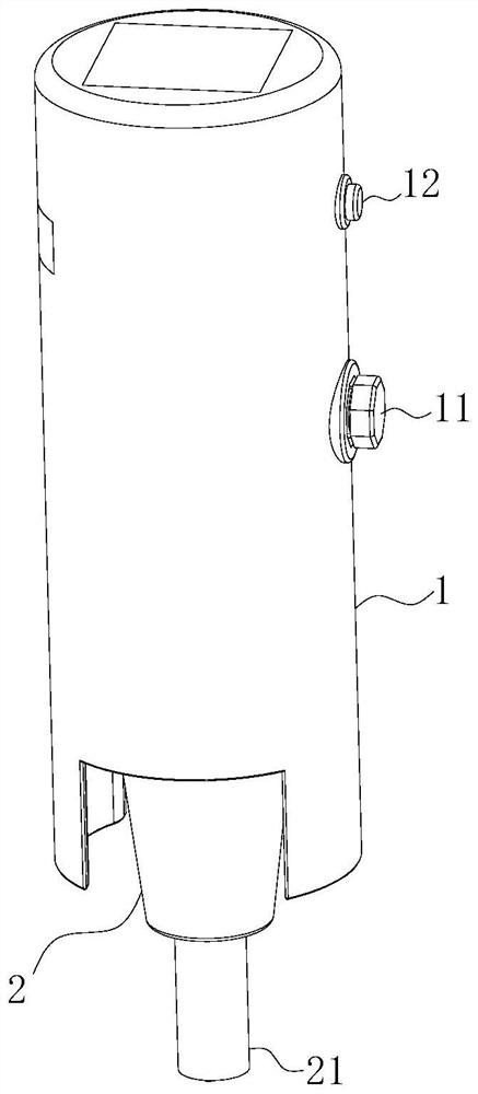
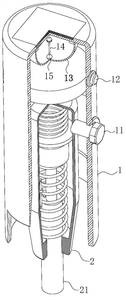
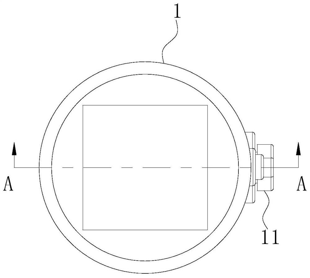
[0026] Such as Figure 1 to Figure 8 As shown, a device for detecting compressive strength of building concrete according to the present invention includes a casing 1, a casing 2 and an adjustment column 3; the casing 1 is designed as a cylindrical structure; cavity; the lower surface of the housing 1 is provided with an adjustment port; the housing 1 is symmetrically provided with avoidance openings in the front and rear directions of the adjustment port position; the inside of the housing 1 is provided with a casing 2, and the casing 2 is a cylindrical structure Design; the outer arc surface of the casing 2 is fixedly connected with an adjustment column 3 near the upper surface of the casing 2; the number of the adjustment columns 3 is two, and ...


PUM


Abstract

The invention belongs to the technical field of civil construction engineering, and particularly relates to a building concrete compressive strength detection device which comprises a shell, a machineshell and an adjusting column. A machine shell is arranged in the shell, and the machine shell is of a cylinder structure. An adjusting column is fixedly connected to the position, close to the uppersurface of the machine shell, of the outer arc face of the machine shell, and the adjusting column is rotationally connected with the shell. Effective detection of the concrete surface compressive strength in the inclined state is effectively achieved, meanwhile, the concrete inclination angle specific corresponding numerical value can be effectively and synchronously detected in the detection process, effective conversion of the later compressive strength detection numerical value is facilitated, the situation that special angle detection on the concrete surface cause inconvenience in detection personnel, and the workload of the detection personnel is greatly improved can be avoided, The device has the advantages of simple structure, easiness in operation, no great increase of the weightof the rebound apparatus, convenience in carrying and detection at any time.

Description

technical field [0001] The invention belongs to the technical field of civil construction engineering, in particular to a detection device for the compressive strength of building concrete. Background technique [0002] The basic principle of the rebound tester is to use a spring to drive the heavy hammer, and the heavy hammer hits the bullet rod in vertical contact with the concrete surface with constant kinetic energy, so that the local concrete deforms and absorbs part of the energy, and the other part of the energy is converted into the rebound kinetic energy of the heavy hammer , when all the kinetic energy of the rebound is converted into potential energy, the weight rebounds to the maximum distance, and the instrument displays the maximum rebound distance of the weight in the name of the rebound value (the ratio of the maximum rebound distance to the initial length of the spring). [0003] According to CN108844839A a rebound hammer, in the prior art, when the rebound ...

Claims


Application Information

Patent Timeline
Patent Type & Authority Applications(China)
IPC IPC(8): G01N3/52G01N3/02G01N3/06
CPCG01N3/02G01N3/06G01N3/52
Inventor 不公告发明人
Owner 刘玉荣
Why Eureka
Try Eureka