
Independent material discharging machine outside machine tool

A technology of machine tool and material machine, which is applied in the field of independent discharge machine outside the machine tool, which can solve the problems of inconvenient operation on the machine, and achieve the effects of avoiding mutual collision damage, avoiding collision, reasonable storage and collection

Pending Publication Date: 2020-11-06
DALIAN XINGANG HYDRAULIC PIPE FITTING
View PDF0 Cites 0 Cited by
  • Summary
  • Abstract
  • Description
  • Claims
  • Application Information

AI Technical Summary

Problems solved by technology

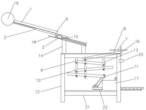
[0003] For this reason, the embodiment of the present invention provides an independent discharger outside the machine tool, which is independent of the machine tool through the whole set of mechanisms, and only a few circuit signals are connected to the machine tool without other structural connections, which is convenient for quick movement and production adjustment, and because The entire material receiving process is entered when the machine tool is shut down, and the mechanism is withdrawn when the machine tool is working, so it can greatly avoid the disturbance of automation stability caused by uncertain factors such as iron cutting, reasonable material storage and collection, avoid bumping, and maximize the Reduce the time for personnel to cooperate with packing to solve the problem that too many mechanisms in the prior art are connected to the machine tool, which makes it inconvenient for personnel to operate on the machine and intersperses the problem of small batch production

Method used


Image

  • Independent material discharging machine outside machine tool
  • Independent material discharging machine outside machine tool
  • Independent material discharging machine outside machine tool

Examples


Embodiment Construction

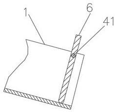
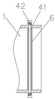
[0028] The implementation mode of the present invention is illustrated by specific specific examples below, and those who are familiar with this technology can easily understand other advantages and effects of the present invention from the contents disclosed in this description. Obviously, the described embodiments are a part of the present invention. , but not all examples. Based on the embodiments of the present invention, all other embodiments obtained by persons of ordinary skill in the art without making creative efforts belong to the protection scope of the present invention.

[0029] Refer to the attached Figure 1-4, an independent discharge machine outside the machine tool in this embodiment, including a frame 12, two fixed legs 14 are fixed on the top of the frame 12, and a cylinder line rail fixing plate is fixed on the top of the fixed legs 14 18. The top of the cylinder rail fixing plate 18 is fixed with a reciprocating rail 15, the reciprocating rail 15 is prov...


PUM


Abstract

The invention discloses an independent material discharging machine outside a machine tool and particularly relates to the technical field of material discharging. The independent material dischargingmachine comprises a rack. Two fixing supporting legs are fixedly arranged at the top end of the rack, and an air cylinder line rail fixing plate is fixedly arranged at the top ends of the fixing supporting legs. A reciprocating line rail is fixedly arranged at the top end of the air cylinder line rail fixing plate, and a reciprocating motion rodless air cylinder is arranged on the reciprocating line rail. A reciprocating motion air cylinder is fixedly arranged at the top end of the reciprocating motion rodless air cylinder, and an inclined material receiving groove is fixedly formed in the top end of the reciprocating motion air cylinder. By means of the independent material discharging machine, the whole set of mechanism is independently arranged outside the machine tool, only several circuit signals are connected with the machine tool, connection of other structures does not exist, fast moving is facilitated, and production adjustment is facilitated; due to the fact that the whole material receiving process is conducted only the machine tool is shut down and the mechanism retreats when the machine tool works, the trouble of uncertain factors such as filings on automatic stability is avoided to a great degree; and reasonable material storage and collection are achieved, colliding is avoided, and the time that people need to cooperate for boxing is also reduced to the maximumdegree.

Description

technical field [0001] The embodiment of the present invention relates to the technical field of discharge, and in particular to an independent discharge machine outside a machine tool. Background technique [0002] Under the background of the current automation trend, there are many automations that solve the nesting problem of small parts, but there are not many nesting methods for long shafts, and most of them cannot solve the problem of bump damage, iron cutting obstruction, and use When the output of automated products is insufficient, too many mechanisms are connected to the machine tool, which makes it inconvenient for personnel to operate on the machine, interspersed with small batch production, so an independent discharger outside the machine tool is needed. Contents of the invention [0003] For this reason, the embodiment of the present invention provides an independent discharger outside the machine tool, which is independent of the machine tool through the who...

Claims


Application Information

Patent Timeline
Patent Type & Authority Applications(China)
IPC IPC(8): B23Q7/00B23Q7/08
CPCB23Q7/00B23Q7/003B23Q7/08
Inventor 龙镜淇
Owner DALIAN XINGANG HYDRAULIC PIPE FITTING
Learn More