Supercharge Your Innovation With Domain-Expert AI Agents!

A special optical mold and its assembly process and use method

An optical and mold technology, applied in the optical field, can solve the problems of high finished product, unfavorable filter selector mold popularization, and inability to control the angle.

Active Publication Date: 2021-07-20
安徽贝仕达光学科技有限公司
View PDF0 Cites 0 Cited by
  • Summary
  • Abstract
  • Description
  • Claims
  • Application Information

AI Technical Summary

Problems solved by technology

The role of the filter selector mold in practical applications is very obvious. However, the current filter selector mold has a complex structure, and the finished product is very high. Moreover, the individual control of the filter cannot be completed, and the overall operation skills are also affected. The requirements are very strict, which is not conducive to the popularization of the use of filter selector molds, and some optical operations require special requirements for the angle of light, which requires the filter to be able to adjust the angle, but the existing devices are basically horizontal The setting of the position cannot effectively control the angle. Even if the angle can be adjusted, the accuracy of the angle cannot meet the actual needs. Therefore, there is an urgent need for an efficient and accurate filter selector mold that is easy to operate and control. needs

Method used


Image

  • A special optical mold and its assembly process and use method
  • A special optical mold and its assembly process and use method
  • A special optical mold and its assembly process and use method

Examples


Embodiment Construction

[0028] The present invention will be further described below in conjunction with specific examples.

[0029] The present invention will be described in detail below in conjunction with specific embodiments shown in the accompanying drawings. However, these embodiments do not limit the present invention, and any structural, method, or functional changes made by those skilled in the art according to these embodiments are included in the protection scope of the present invention. The application principle of the present invention will be further described below in conjunction with the accompanying drawings and specific embodiments.

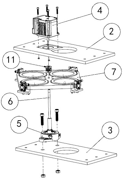
[0030] The filter mechanism is an important component such as an area array staring camera. It needs to switch filters frequently during the entire life cycle of the camera in orbit to cooperate with the multi-spectral imaging work of the whole machine, and this part is usually a single point of failure of the camera. link. Therefore, ensuring the ...


PUM


Abstract

An optical special mold is disclosed, which includes a mold support, an upper platform plate and a lower platform plate are installed on the mold support, a driving device is arranged on the upper platform plate, a rotating component is arranged on the lower platform plate, and a driving rod group is connected to the driving device. Between the drive rod group and the rotating assembly, an optical runner is assembled, each assembly hole of the optical runner is equipped with a filter bracket, the filter bracket is installed with an optical filter, and the optical runner is provided with Several rotating devices, the rotating device can make the filter holder rotate, the optical wheel is also provided with a support device, the support device can provide support for the rotating device, and the optical wheel can follow the drive rod group to rotate, so that the filter can be rotated. Located between the upper working notch and the lower working notch, it can meet the requirements of optical operation with high quality, and can effectively perform filter switching and filter tilting operation, and the precision is compounded.

Description

technical field [0001] The invention relates to the field of optics, more specifically, to an optical special mold and its assembly process and usage method. Background technique [0002] The optical filter is an optical device used to select the required radiation band. In the actual work process, in order to obtain detailed spectral information and achieve the required imaging effect, it is necessary to filter the light entering the system so that the specific spectral band Light passes through the filter for imaging, while light from other spectral bands is cut off. Therefore, it is necessary to design a filter mechanism to realize the switching of different required light rays. In order to ensure the fusion quality of different image information, the positioning accuracy and repeatability accuracy of the filter should be improved as much as possible. [0003] Filter selector stencils are commonly used instruments in the process of using filters, and they are implemented...

Claims


Application Information

Patent Timeline
Patent Type & Authority Patents(China)
IPC IPC(8): G02B7/00
CPCG02B7/006
Inventor 黄玉成
Owner 安徽贝仕达光学科技有限公司
Features
  • R&D
  • Intellectual Property
  • Life Sciences
  • Materials
  • Tech Scout
  • Unparalleled Data Quality
  • Higher Quality Content
  • 60% Fewer Hallucinations
Learn More