
Lens driving mechanism, lens driving device, photographic device, and electronic equipment

A technology of lens driving and driving frame, which is applied in the fields of lens driving device, camera device, electronic equipment and lens driving mechanism, can solve the problems such as the non-functioning of the anti-shake motor and the falling off of balls, so as to improve the convenience of assembly and improve the anti-shake performance. performance effect

Pending Publication Date: 2020-11-06
NEW SHICOH MOTOR CO LTD
View PDF0 Cites 1 Cited by
  • Summary
  • Abstract
  • Description
  • Claims
  • Application Information

AI Technical Summary

Problems solved by technology

[0004] Due to the translational structure of the existing translational anti-shake motor, balls are used to drive the main body to move, but during use, when vibrating or shaking, the balls are prone to fall off, resulting in the anti-shake motor not working normally

Method used


Image

  • Lens driving mechanism, lens driving device, photographic device, and electronic equipment
  • Lens driving mechanism, lens driving device, photographic device, and electronic equipment
  • Lens driving mechanism, lens driving device, photographic device, and electronic equipment

Examples


Embodiment 1

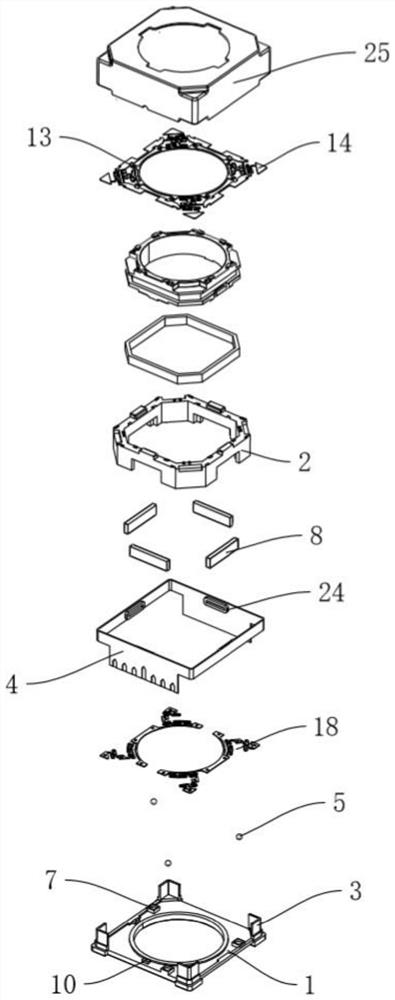
[0030] Embodiment 1: as Figure 1 to Figure 6 As shown, an anti-shake structure proposed by the present invention includes a housing 25, a base 1, and a frame body 2 connected to the driving body. A moving assembly and a driving assembly are arranged between the base 1 and the frame body 2. Four Brackets 3 are integrally formed at corner positions, and FPC boards 4 are connected between the four brackets 3 .

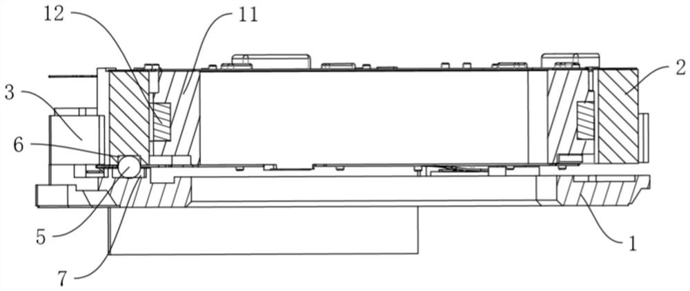
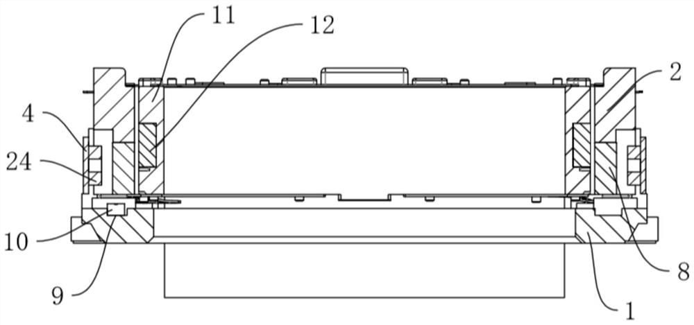
[0031] The moving assembly includes three balls 5 arranged between the base 1 and the frame body 2, an accommodating groove 6 set on the bottom surface of the frame body 2 and accommodating the balls 5, and a movable groove set on the base 1 for the relative movement of the balls 5 7. The diameter of the movable groove 7 is larger than that of the ball 5 , and the ball 5 is movable relative to the movable groove 7 . The frame body 2 is stably supported by three balls 5, and the balls 5 move in the movable groove 7 to facilitate the translation of the frame body 2 relati...

Embodiment 2

[0036] Embodiment 2: a kind of lens driving device, such as Figure 7 As shown, it has the lens driving mechanism described in Embodiment 1, and also includes a driving body connected to the frame body 2. The driving body includes a carrier 11 that is arranged in the frame body 2 and can move relative to the frame body 2, and is arranged on the carrier body 11. And drive coils 12 corresponding to the four magnets 8 . The inner grouping 13 of the upper spring is arranged between the end of the carrier 11 facing away from the base 1 and the frame body 2 , and the inner fixing part of the lower spring is connected to the end of the carrier 11 facing the base 1 .

Embodiment 3

[0037] Embodiment 3: a photographic device having the lens driving device described in Embodiment 2.


PUM


Abstract

The invention discloses a lens driving mechanism, a lens driving device, a photographic device and electronic equipment. According to the technical scheme, the lens driving mechanism comprises a shell, a base and a frame body connected to a driving main body, a moving assembly is arranged between the base and the frame body, the moving assembly comprises at least three rolling beads arranged between the base and the frame body, a containing groove formed in the bottom face of the frame body and used for containing the rolling beads, and a movable groove formed in the base and used for the rolling beads to move relatively, an upper spring set and a lower spring set which have potential energy for driving the frame body to move towards the base are arranged between the frame body and the base, and the upper spring set and the lower spring set are arranged at the two ends of the frame body respectively. According to the invention, the frame body is stably supported through the three rolling beads to achieve frame body translation, and the potential energy for driving the frame body to move towards the base is formed through the height difference between the installation positions of the upper spring set and the lower spring set, so that it is ensured that the rolling beads are located in the containing groove, the rolling beads are effectively prevented from falling off, and the assembly reliability is improved.

Description

technical field [0001] The invention relates to the field of photographic equipment, in particular to a lens driving mechanism, a lens driving device, a photographing device and electronic equipment. Background technique [0002] The optical anti-shake performance of the camera module of electronic equipment has attracted more and more attention. The anti-shake motor is an optical anti-shake device. The camera module is generally installed on the anti-shake motor. The anti-shake motor can effectively reduce the Eliminate the chance of blurry photos in the environment, and reduce the unavoidable shaking during video or photo shooting. [0003] The existing anti-shake motors mainly include shift OIS and Tilt OIS; and the structure of the anti-shake motor can be divided into translation type, shifting shaft type, memory metal (SMA) type, etc. according to different structures; the main structure of the anti-shake motor is the driving body with lens drive mechanism. [0004] T...

Claims


Application Information

Patent Timeline
Patent Type & Authority Applications(China)
IPC IPC(8): G02B7/02G03B5/00
CPCG02B7/02G03B5/00
Inventor 刘华
Owner NEW SHICOH MOTOR CO LTD
Features
  • Generate Ideas
  • Intellectual Property
  • Life Sciences
  • Materials
  • Tech Scout
  • Unparalleled Data Quality
  • Higher Quality Content
  • 60% Fewer Hallucinations
Learn More