
A Distributed Energy Storage Capacity Configuration Method Aiming at Reducing Transformer Capacity Expansion

A technology of distributed energy storage and energy storage capacity, applied in the field of distributed energy storage capacity configuration, can solve the problems of high input cost and low utilization rate of new equipment

Active Publication Date: 2022-03-11
浙江华云清洁能源有限公司
View PDF6 Cites 0 Cited by
  • Summary
  • Abstract
  • Description
  • Claims
  • Application Information

AI Technical Summary

Problems solved by technology

[0004] Aiming at the problem of transformer overload, the current commonly used measures are to increase the capacity of distribution equipment (that is, to expand the distribution transformer) or completely use distributed energy storage to meet the needs of transformers when the overload is the most serious, so as to solve the problem of transformer overload. , however, relying only on capacity expansion or distributed energy storage to meet transformer overload will not only have the problem of relatively high investment costs, but also have the problem of low utilization of new equipment

Method used


Image

  • A Distributed Energy Storage Capacity Configuration Method Aiming at Reducing Transformer Capacity Expansion
  • A Distributed Energy Storage Capacity Configuration Method Aiming at Reducing Transformer Capacity Expansion
  • A Distributed Energy Storage Capacity Configuration Method Aiming at Reducing Transformer Capacity Expansion

Examples


Embodiment Construction

[0061] The following will clearly and completely describe the technical solutions in the embodiments of the application with reference to the drawings in the embodiments of the application. Apparently, the described embodiments are only some of the embodiments of the application, not all of them. Based on the embodiments in this application, all other embodiments obtained by persons of ordinary skill in the art without making creative efforts belong to the scope of protection of this application.

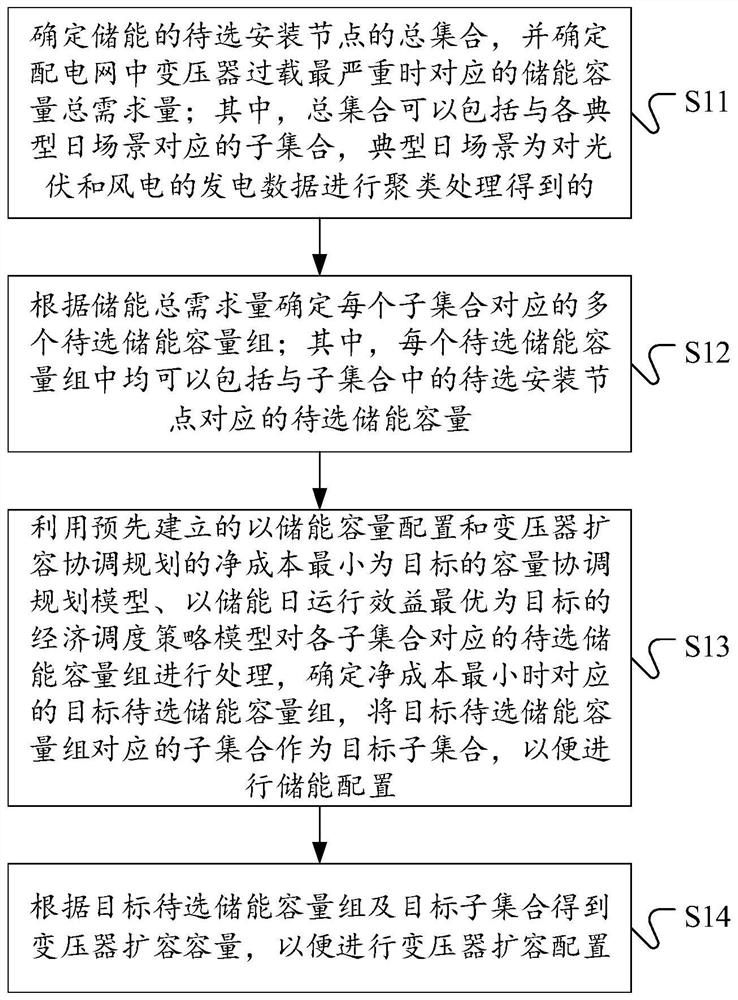
[0062] see figure 1 , which shows a flow chart of a distributed energy storage capacity configuration method aimed at reducing transformer capacity expansion provided by an embodiment of the present application. Energy storage capacity allocation methods may include:

[0063] S11: Determine the total set of candidate installation nodes for energy storage, and determine the total demand for energy storage capacity corresponding to the most severe transformer overload in the distribu...


PUM


Abstract

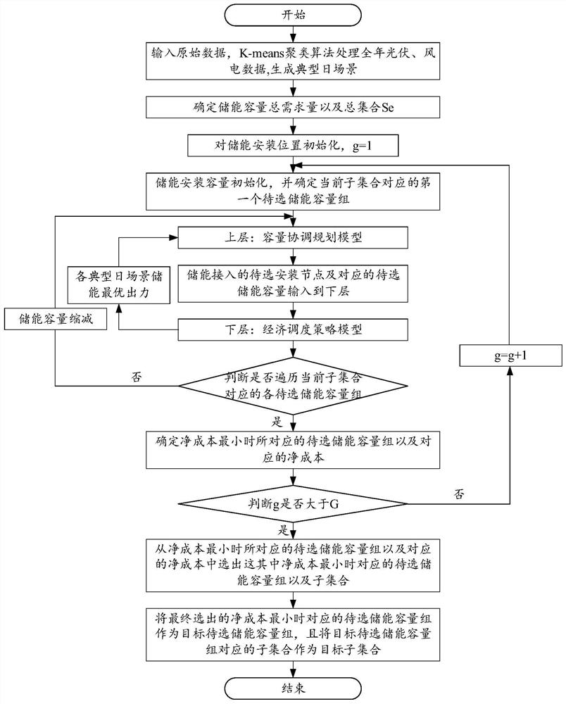
The present application discloses a distributed energy storage capacity configuration method, device, equipment, and computer-readable storage medium aiming at reducing transformer capacity expansion. The method includes: determining the total set of energy storage nodes to be installed and the energy storage capacity Total demand; determine the energy storage capacity group to be selected corresponding to each subset; use the pre-established capacity coordination planning model with the goal of minimizing the net cost of energy storage capacity configuration and transformer coordination planning, and optimize the daily operation efficiency of energy storage as The target economic dispatch strategy model processes the candidate energy storage capacity groups corresponding to each sub-set, determines the target candidate energy storage capacity group corresponding to the minimum net cost, and takes the target candidate energy storage capacity group corresponding to the target sub-set as the target sub-set set; get the expansion capacity of the transformer according to the target energy storage capacity group to be selected and the target subset. The technical solution disclosed in the application can reduce the capacity expansion of the transformer, reduce the cost of transformer overload treatment, and improve the utilization rate of equipment equipped for transformer overload treatment.

Description

technical field [0001] The present application relates to the technical field of transformer processing, and more specifically, relates to a distributed energy storage capacity configuration method, device, equipment and computer-readable storage medium aiming at reducing transformer capacity expansion. Background technique [0002] With the depletion of fossil energy, environmental problems have become increasingly prominent. Distributed power has been developed rapidly due to its non-polluting advantages. At the same time, EV (Electric Vehicles, electric vehicles) can greatly reduce the use of fossil energy. [0003] The large-scale EV charging behavior or a substantial increase in other power consumption behaviors have greatly increased the peak load. Because the distribution network did not consider the large-scale EV charging demand or other large-scale increase in power consumption behavior before planning, therefore, the configuration The capacity of the transformer ...

Claims


Application Information

Patent Timeline
Patent Type & Authority Patents(China)
IPC IPC(8): H02J3/00H02J3/28
CPCH02J3/00H02J3/28H02J3/008H02J2203/10H02J2203/20Y02E70/30
Inventor 沈宝兴徐一剑陈琦张谓江吴星昂於国芳吕浩华林琳吴慧青俞梅李军徽李翠萍周恒宇马得轩张昊严干贵
Owner 浙江华云清洁能源有限公司
Learn More