Supercharge Your Innovation With Domain-Expert AI Agents!

A porcelain bowl processing and forming machine

A molding machine and porcelain bowl technology, which is applied in ceramic molding machines, auxiliary molding equipment, manufacturing tools, etc., can solve the problems of laborious work, easy hand injury by the circular frame, etc., and achieve the effect of avoiding slipping

Active Publication Date: 2021-10-26
苏州爱柯基科技有限公司
View PDF4 Cites 0 Cited by
  • Summary
  • Abstract
  • Description
  • Claims
  • Application Information

AI Technical Summary

Problems solved by technology

[0005] In order to overcome the disadvantages that hand-held tools need to be in contact with the clay to make it shape, it is laborious, and the circular frame needs to be stopped and fixed by hand, and the hand is easily injured by the circular frame. The technical problem to be solved is to provide a more It is convenient for people to process clay into porcelain bowls, which saves labor, and does not need to fix the round frame by hand, avoiding the porcelain bowl processing and forming machine that hurts hands

Method used


Image

  • A porcelain bowl processing and forming machine
  • A porcelain bowl processing and forming machine
  • A porcelain bowl processing and forming machine

Examples


Embodiment 1

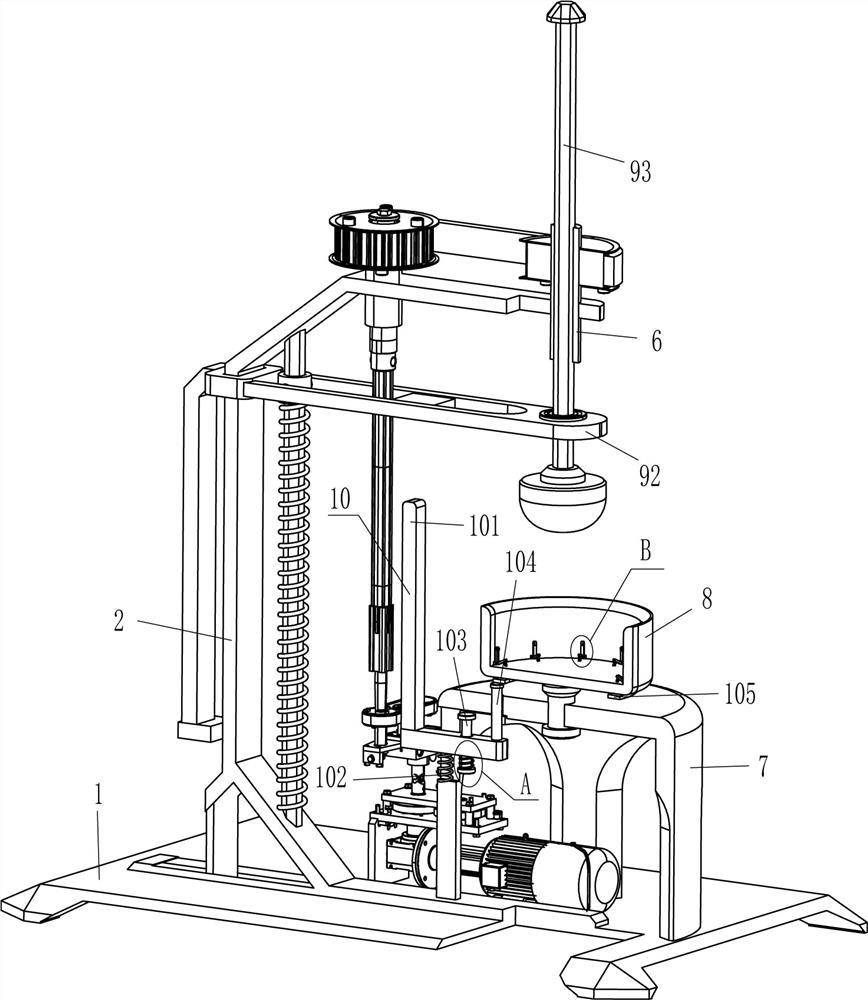
[0022] A porcelain bowl processing and forming machine, such as figure 1 As shown, it includes a base 1, a frame 2, a rotating shaft 3, a geared motor 4, a transmission assembly 5, an inner hexagonal hollow sleeve 6, a support platform 7, a circular frame 8 and a processing device 9, and the front part on the right side of the top of the base 1 is fixed. Connected with a support platform 7, a circular frame 8 is connected to the center of the support platform 7 in a rotating manner, the front side of the top of the base 1 is fixedly connected with a frame 2, and the top left side of the frame 2 is rotatably connected with a rotating shaft 3. The right side of the top of the frame 2 is connected with a hexagonal hollow sleeve 6 in a rotating manner. A transmission assembly 5 is connected between the upper circumference of the outer surface of the inner hexagonal hollow sleeve 6 and the top of the rotating shaft 3. The middle of the top right side of the base 1 is connected by bo...

Embodiment 2

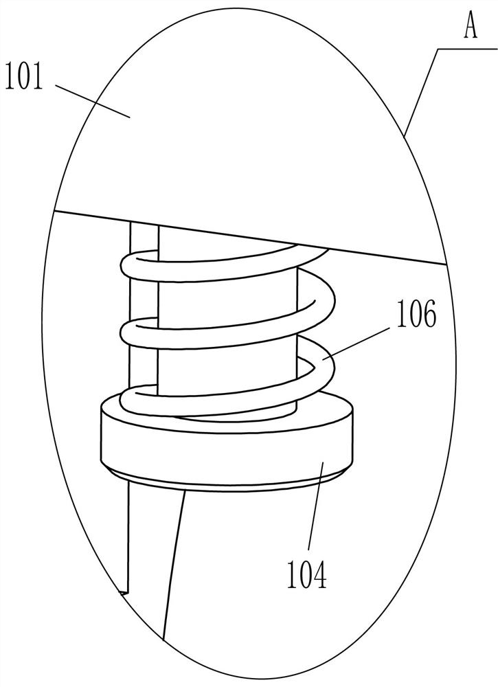
[0027] On the basis of Example 1, such as Figure 1-Figure 3As shown, a clamping mechanism 10 is also included, and the clamping mechanism 10 includes an L-shaped movable plate 101, a second spring 102, a damping rod 103, a contact rod 104, a contact ring 105 and a third spring 106, and the left side of the support platform 7 The upper sliding type is pierced with an L-shaped movable plate 101 that cooperates with the horizontal plate 92. A second spring 102 is connected between the left side of the outer bottom of the L-shaped movable plate 101 and the inside of the support platform 7, and the right part of the L-shaped movable plate 101 slides. There is a damping rod 103 in the threaded connection, the top of the damping rod 103 is in contact with the inner top of the support platform 7, and a third spring 106 is wound between the inner bottom of the damping rod 103 and the outer bottom of the L-shaped movable plate 101, and the outer part of the circular frame 8 A contact r...

Embodiment 3

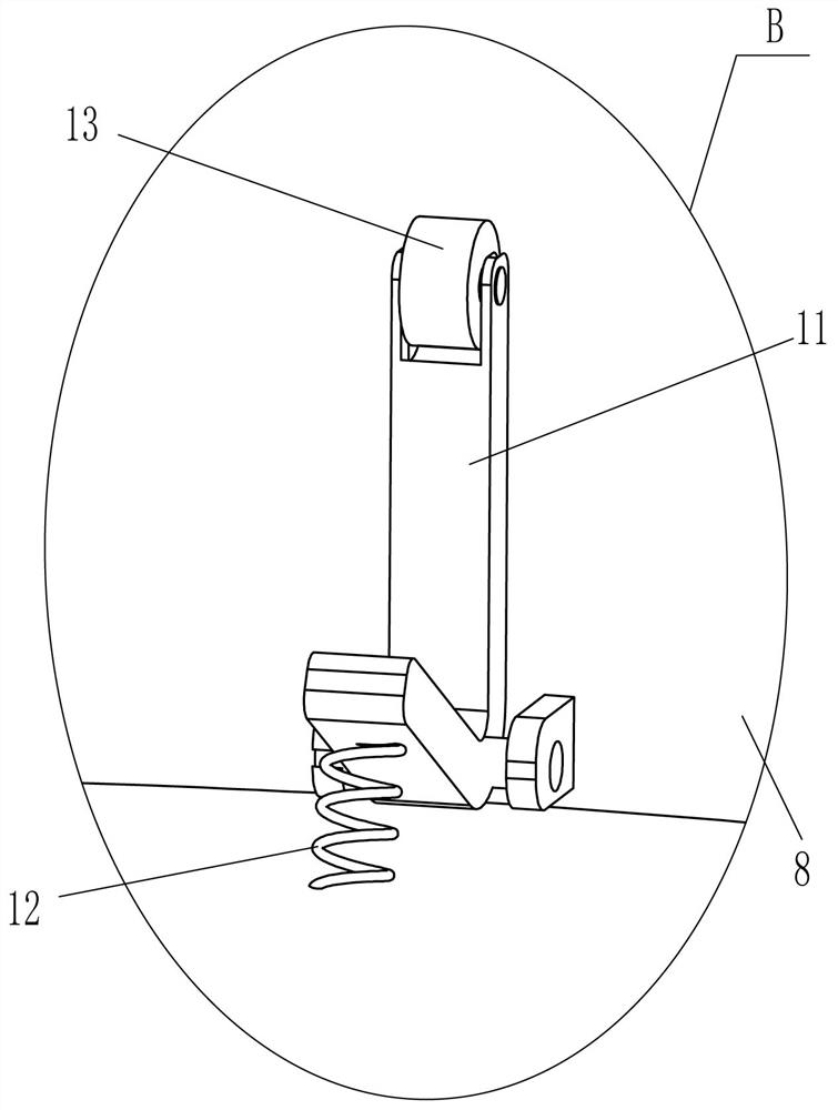
[0030] On the basis of embodiment 1 and embodiment 2, such as figure 2 and Figure 4 As shown, it also includes an L-shaped bar 11 and a fourth spring 12. The L-shaped bar 11 is hinged evenly spaced circumferentially on the lower part of the inner surface of the supporting platform 7, and the inner bottom of the L-shaped bar 11 is connected with the inner bottom of the supporting platform 7. The fourth spring 12 .

[0031] It also includes a contact wheel 13, and the top end of the L-shaped bar 11 is rotatably connected with the contact wheel 13.

[0032] When the container that pottery clay is housed is put into circular frame 8, when container contacts with L-shaped bar 11, container drives L-shaped bar 11 inner end to swing downwards, and the 4th spring 12 compresses, and L-shaped bar 11 inner end The lower swing makes the top swing inward, and the top of the L-shaped bar 11 swings inward to contact the container to fix it. When the clay is processed into a porcelain bo...


PUM


Abstract

The invention relates to a forming machine, in particular to a porcelain bowl processing and forming machine. The technical problem is how to design a porcelain bowl processing and molding machine that can be more convenient for people to process pottery clay into porcelain bowls, saves labor, and does not need to fix the circular frame by hand, avoiding hands being injured. A porcelain bowl processing and forming machine, comprising: a base, a support platform is fixedly connected to the edge of one side of the base, and a circular frame is rotatably connected to the center of the side of the base far away from the base; a frame, the The frame is fixed on one side of the base. In the present invention, by putting the container with clay into the circular frame and starting the deceleration motor, the hexagonal rod can drive the semicircle to rotate, and then step on the pedal to move downward, and the semicircle will move downward and pass through the contact with the clay. The container enables it to be processed and shaped, and there is no need for a hand-held tool to be in contact with the clay to form it, which is labor-saving.

Description

technical field [0001] The invention relates to a forming machine, in particular to a porcelain bowl processing and forming machine. Background technique [0002] Porcelain bowls: Porcelain bowls in different periods have obvious differences in shape, glaze and decoration. The bowls before the Tang Dynasty were mostly straight-mouthed, flat-bottomed, glazed to the bottom, and basically without decoration. There are many types of bowls in the Tang Dynasty, such as straight mouth, skimming mouth, sunflower mouth, etc., with lip protruding along the mouth, mostly flat bottom, jade wall bottom and ring-shaped bottom. The glaze is close to the bottom, and the refined products are covered with glaze. , there are simple scratch decorations. When the porcelain bowls are processed, they are all shaped by clay, so that the clay is processed into porcelain bowls for subsequent operations. [0003] At present, most of the pottery clay is processed into porcelain bowls through the coop...

Claims


Application Information

Patent Timeline
Patent Type & Authority Patents(China)
IPC IPC(8): B28B1/02B28B17/00
CPCB28B1/02B28B17/00
Inventor 陈丹丹
Owner 苏州爱柯基科技有限公司
Features
  • R&D
  • Intellectual Property
  • Life Sciences
  • Materials
  • Tech Scout
  • Unparalleled Data Quality
  • Higher Quality Content
  • 60% Fewer Hallucinations
Learn More