
Novel electro-hydraulic combined braking system and braking method thereof

A braking system and electronic braking technology, applied in the direction of braking transmission device, braking action activation device, brake, etc., can solve the problem that the driver's pedal feeling experience is not very good, the vehicle loses the braking ability, and the vehicle is unsafe and other issues, to achieve the effect of exerting energy recovery ability, improving safety and high safety performance

Pending Publication Date: 2020-11-10
GELUBO TECH CO LTD
View PDF9 Cites 4 Cited by
  • Summary
  • Abstract
  • Description
  • Claims
  • Application Information

AI Technical Summary

Problems solved by technology

For example, patent No. 201711059529.0 "An Electric Brake Booster for Automobiles" is an electric booster with a decoupling structure due to the existence of idle travel, so the driver's pedal feeling experience is not very good when braking. In order to solve the problem of pedal Some manufacturers will install simulated springs at the position of the brake pedal push rod, such as Patent No. 201910769731.5 "A Pedal Simulator". Although this simulated decoupling can improve the pedal feel to a certain extent, due to the spring stiffness in a The product cannot be adjusted according to the working conditions of the vehicle
[0005] When all four wheels use electronic brake calipers, when the electronic control system fails and there is no mechanical brake as a backup, the vehicle will lose its braking ability and the vehicle will be in an unsafe state
With the traditional four-wheel full hydraulic system, the parking brake requires an additional parking mechanism

Method used

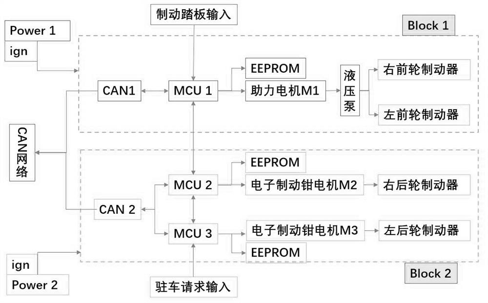
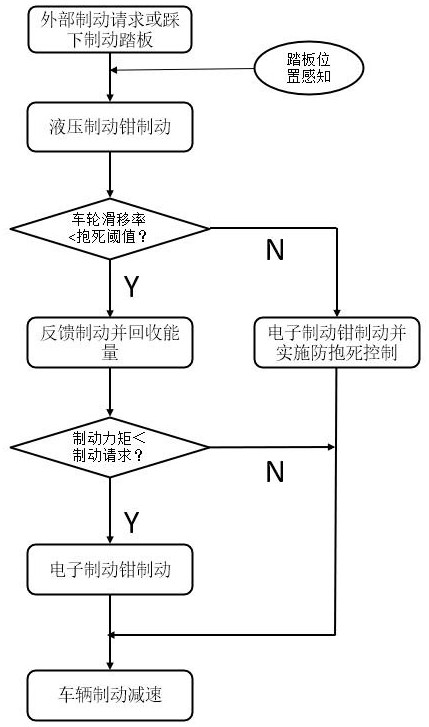

Image

  • Novel electro-hydraulic combined braking system and braking method thereof
  • Novel electro-hydraulic combined braking system and braking method thereof
  • Novel electro-hydraulic combined braking system and braking method thereof

Examples


Embodiment Construction

[0042] The specific implementation manners of the present invention will be further described below in conjunction with the accompanying drawings, and this embodiment does not constitute a limitation to the present invention.

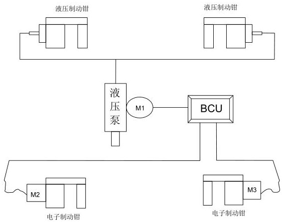
[0043] A new electro-hydraulic combined braking system, such as figure 1 As shown, it includes two hydraulic brake calipers installed on the front / rear axle of the vehicle, and two electronic brake calipers installed on the rear / front axle of the vehicle. Specifically, in order to cooperate with braking energy recovery, the electronic brake caliper is installed on the drive shaft, and the hydraulic brake caliper is installed on the other shaft;

[0044] Such as figure 1 As shown, that is, when the vehicle power motor is installed on the front axle, that is, the front drive of the vehicle, the electronic brake caliper is installed on the front axle, and the hydraulic brake caliper is installed on the rear axle;

[0045] When the vehicle power motor is ...


PUM


Abstract

The invention discloses a novel electro-hydraulic combined braking system, relates to the technical field of automobile braking systems, and solves the problems that the pedal feeling experience is poor, no mechanical braking is used as a backup, and the safety is low when the traditional automobile braking system is used for recovering braking energy. The device comprises two hydraulic brake calipers mounted on a front / rear axle of a vehicle, and two electronic brake calipers mounted on a rear / front axle of the vehicle, the hydraulic brake caliper is connected to a hydraulic pump used for providing hydraulic pressure, and the hydraulic pump is connected with a power-assisted motor used for providing assisting power. The electronic brake caliper comprises an electronic brake motor for providing power; the power-assisted motor and the electronic brake motor are both connected to a controller BCU, and the controller BCU controls operation of the power-assisted motor and the brake motor.And the effects of facilitating braking energy recovery and safe backup braking are achieved.

Description

technical field [0001] The invention relates to the technical field of automobile braking systems, in particular to a novel electro-hydraulic combined braking system and a braking method thereof. Background technique [0002] The traditional vehicle braking system is generally hydraulic braking, that is, the front and rear axles are hydraulic brake calipers or brake drums. When working, a brake master cylinder is required, and the brake master cylinder is in the form of a double chamber. In traditional vehicles, it is generally Vacuum boost is used as the source of brake boost. This form of boost will cause insufficient vacuum when the engine is at a plateau or at low speed, resulting in a decrease in braking force. On new energy vehicles, there is no engine to provide a vacuum source, and an additional vacuum pump is required to provide vacuum for the booster. This electronic vacuum pump also needs to be equipped with a vacuum tank when it is working, and the vacuum pump wi...

Claims


Application Information

Patent Timeline
Patent Type & Authority Applications(China)
IPC IPC(8): B60T13/58B60T13/74B60T7/04B60T8/1761
CPCB60T7/042B60T8/1761B60T13/58B60T13/74
Inventor 李勋顾勤冬刘兆勇
Owner GELUBO TECH CO LTD
Learn More