Winding core shaft of small roll cutting machine

A technology of slitting machine and winding mandrel, which is applied in the direction of winding strips, thin material processing, transportation and packaging, etc., can solve the problems of unfavorable core size adjustment, low efficiency, etc., and achieves simple structure, convenient use and fast speed. The effect of disassembly

Pending Publication Date: 2020-11-10
SHANGHAI GUANGPING PRINTING EQUIP
View PDF0 Cites 0 Cited by
  • Summary
  • Abstract
  • Description
  • Claims
  • Application Information

AI Technical Summary

Problems solved by technology

[0002] The small roll slitting machine is a mechanical device that can cut a certain width of paper into multiple narrow width materials according to the setting. In the technical field of paper slitting, the existing small roll slitter is through several Set the slitting knife in turn to cut the wide paper, and finally roll the slit narrow paper into several small rolls through the rolling operation. However, in the process of making small rolls, it is often necessary to adjust the core The core is pre-installed on the core shaft, that is, the empty core is pre-assembled on the core shaft, and then each small roll of paper is rolled. The existing core shafts are often fixed and fixed with locking blocks and bolts at both ends. , for a large number of small rolls in the production process, it is often necessary to repeatedly disassemble the locking block, etc., resulting in low efficiency and is not conducive to the size adjustment of the core

Method used


Image

  • Winding core shaft of small roll cutting machine
  • Winding core shaft of small roll cutting machine
  • Winding core shaft of small roll cutting machine

Examples


Embodiment approach

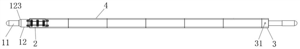
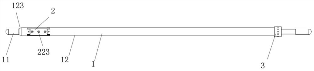
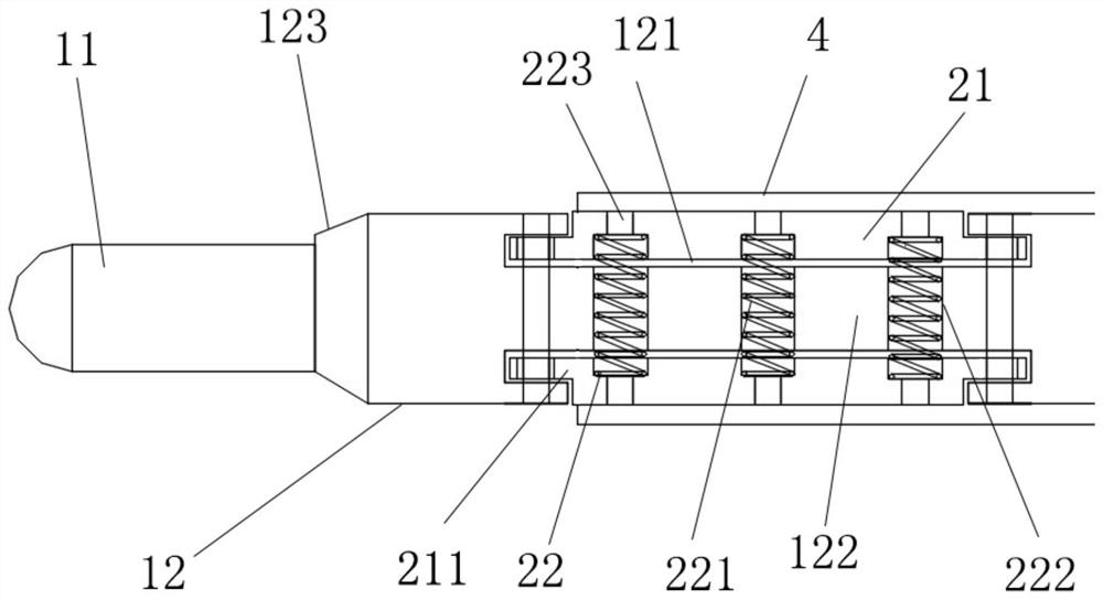
[0029] In a further embodiment of the present invention, the connection between each support section 11 and the installation section 12 is arranged as a truncated cone structure 123, and the diameter of the end of the truncated cone structure 123 near the installation section 12 is larger than that of the end of the truncated cone structure 123 near the support section 11. diameter at one end.

[0030] In a further embodiment of the present invention, the diameters of the two support sections 11 are both smaller than the diameter of the installation section 12 . Further, in order to better complete the production of small roll materials and to facilitate the assembly of the winding core 4, the diameter of the supporting section 11 is smaller than that of the installation section 12, so as to play a guiding role when the winding core 4 is loaded.

[0031]In a further embodiment of the present invention, the positioning ring 3 has a circular ring structure, the positioning ring ...


PUM


Abstract

The invention discloses a winding core shaft of a small roll cutting machine. The winding core shaft comprises a main mandrel body, a telescopic jacking piece, a positioning ring and a plurality of winding cores; the main mandrel body is of a rod-shaped structure; the positioning ring is fixedly installed at one end of the main mandrel body; the telescopic jacking piece is fixedly installed at theother end of the main mandrel body; the plurality of winding cores are sequentially arranged on the main mandrel body in a sleeving manner, one winding core close to one end of the main winding corebody abuts against the positioning ring, and one winding core close to the other end of the main winding core body is clamped on the telescopic jacking piece; and the telescopic jacking piece is arranged in a pressing and telescopic manner in the radial direction of the main mandrel body. Through application of the winding core shaft, rapid winding core pre-assembling work can be conducted, and rapid disassembling can also be conducted, so that the production efficiency of small roll materials such as paper rolls is greatly improved, and waste of labor force is avoided.

Description

technical field [0001] The invention relates to the technical field of printing equipment, in particular to a mandrel for a small roll slitting machine. Background technique [0002] The small roll slitting machine is a mechanical device that can cut a certain width of paper into multiple narrow width materials according to the setting. In the technical field of paper slitting, the existing small roll slitter is through several Set the slitting knife in turn to cut the wide paper, and finally roll the slit narrow paper into several small rolls through the rolling operation. However, in the process of making small rolls, it is often necessary to adjust the core The core is pre-installed on the core shaft, that is, the empty core is pre-assembled on the core shaft, and then each small roll of paper is rolled. The existing core shafts are often fixed and fixed with locking blocks and bolts at both ends. , For the production process of a large number of small rolls, it is often...

Claims


Application Information

Patent Timeline
Patent Type & Authority Applications(China)
IPC IPC(8): B65H19/30B65H18/02B65H75/24
CPCB65H18/028B65H19/305B65H75/245B65H2701/1133
Inventor 贺志红杨泽张军
Owner SHANGHAI GUANGPING PRINTING EQUIP
Why Eureka
Try Eureka