High-speed raising machine raising assembly
A raising machine, high-speed technology, applied in textiles and papermaking, fabric surface trimming, roughening, etc., can solve problems such as poor cylinder strength and difficult processing, and achieve product quality assurance, save manpower and material resources, and shock resistance. Effect of Reliability Improvement
Active Publication Date: 2022-06-03
LIANYUNGANG CHUNJIANG MACHINERY
View PDF6 Cites 0 Cited by
- Summary
- Abstract
- Description
- Claims
- Application Information
AI Technical Summary
Problems solved by technology
Existing domestic and foreign cylinder processing is made of castings or steel parts, and the thickness of the material is selected from 40-50mm according to different models. The disadvantage is that the cylinder strength is poor and the processing is difficult.
Method used
View moreImage
Smart ImageViewing Examples

Examples
Embodiment Construction
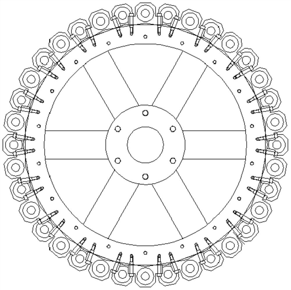
[0023] The mounting surface I and the mounting surface II are both the mounting planes arranged along the tangential direction of the cylinder body.
Login to View More PUM
 Abstract
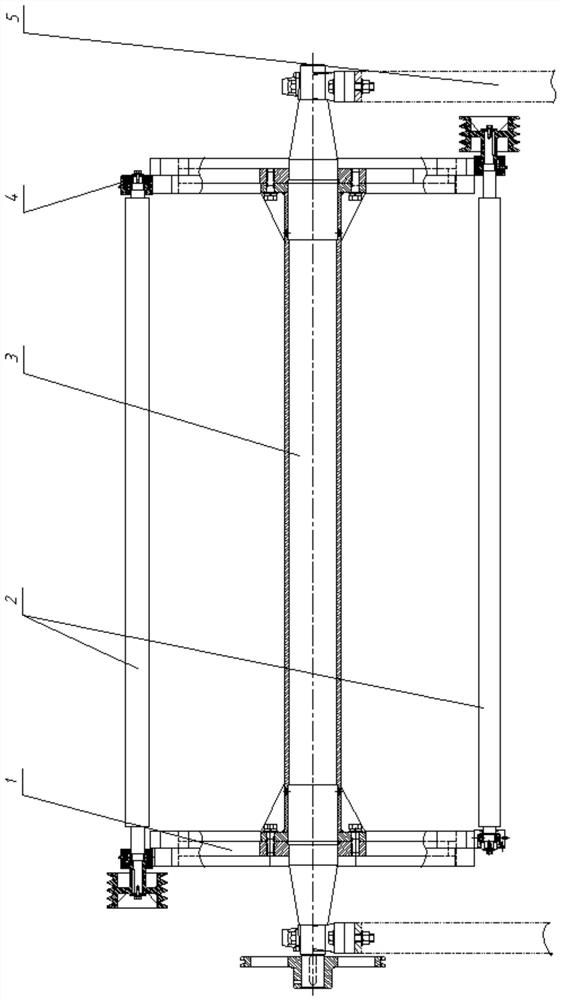
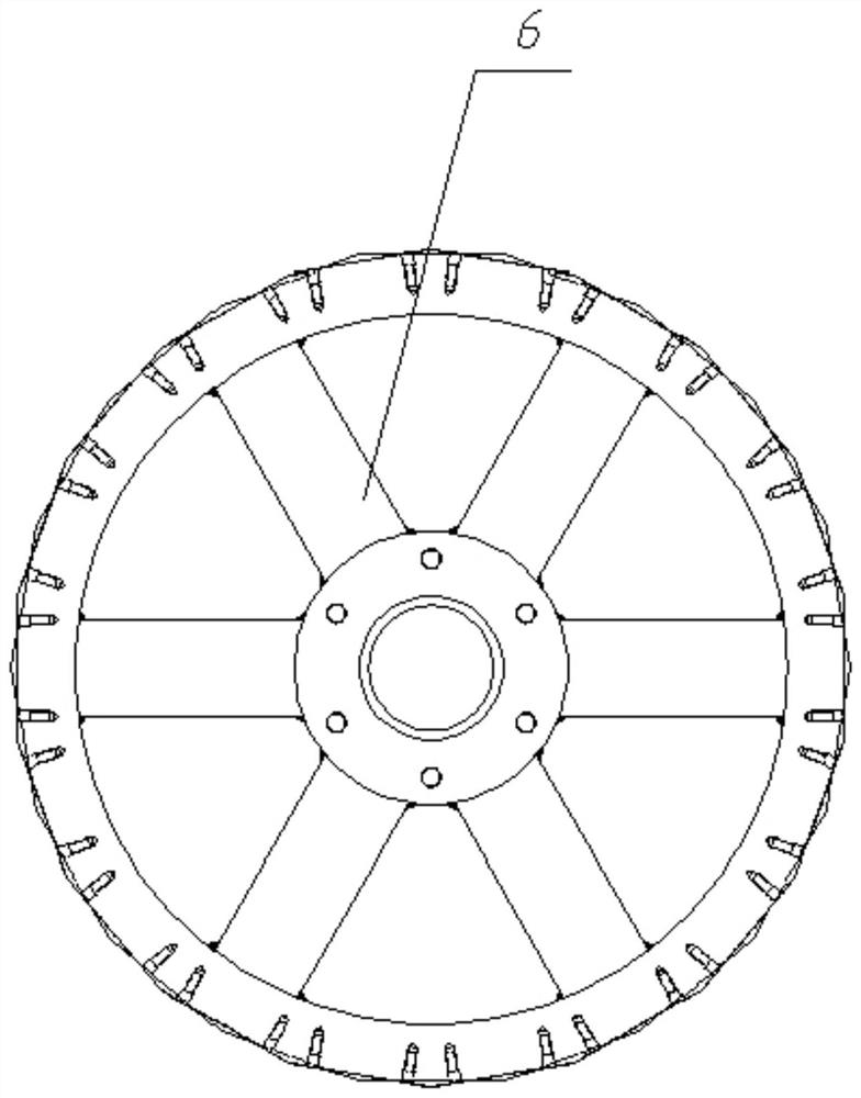
A high-speed raising machine raising assembly, including cylinder plate assembly, raising roller assembly, main shaft, bearing package, raising roller assembly includes raising roller body, driving end of raising roller body is equipped with driving pulley, driving pulley and raising roller The end shaft between the roller bodies is equipped with a power end bearing package, and the end shaft at the free end of the raising roller body is equipped with a free end bearing package. The disk surface and the bearing disk surface of the inner ring, a number of installation surfaces I for installing the above-mentioned power end bearing packages are uniformly arranged on the bearing disk surface of the outer ring, and several installation surfaces for installing the above-mentioned free end bearing packages are uniformly arranged on the bearing disk surface of the inner ring Ⅱ, the number of installation surface I and installation surface II is equal and staggered. By changing and strengthening the structure of the cylinder and changing the different installation positions of the raising roller assembly on the cylinder, the combination strength of the raising assembly is greatly improved, and it has higher safety, stability and reliability.
Description
High-speed raising machine raising assembly technical field The present invention relates to a kind of textile equipment, especially a kind of high-speed raising machine raising assembly. Background technique In the existing domestic and foreign needle roller raising machine raising assembly structure: be installed on two cylinders installed at both ends of the main shaft 24-50 raising roller assemblies, the raising roller assemblies are installed on the same surface of the cylinder at both ends, and the thickness of the cylinder is only 40-50mm, In actual use, the structure is very crowded, and one end of the raising roller and the bearing package is connected by a gap. When the raising force is increased or the strength of raising force is increased, it will cause the bending deformation of raising roller and cylinder, and it is easy to cause some parts after long-term operation. Damage to parts. As a result, the operating speed of the needle roller raising machin...
Claims
Login to View More Application Information
Patent Timeline
 Patent Type & Authority Patents(China)
IPC IPC(8): D06C11/00
CPCD06C11/00
Inventor 姚远杨庆宇
Owner LIANYUNGANG CHUNJIANG MACHINERY
Features
- R&D
- Intellectual Property
- Life Sciences
- Materials
- Tech Scout
- Unparalleled Data Quality
- Higher Quality Content
- 60% Fewer Hallucinations
Learn More Browse by: Latest US Patents, China's latest patents, Technical Efficacy Thesaurus, Application Domain, Technology Topic, Popular Technical Reports.
© 2025 PatSnap. All rights reserved.Legal|Privacy policy|Modern Slavery Act Transparency Statement|Sitemap|About US| Contact US: help@patsnap.com