A method for reducing fuel pressure fluctuations in high-pressure fuel pipes of electronically injected diesel engines

A high-pressure oil pipe, fuel pressure technology, applied in the direction of machine/engine, mechanical equipment, engine components, etc., to save manpower, reduce fluctuations, and have a wide range of applications

Active Publication Date: 2022-03-22
SHANDONG JIAOTONG UNIV
View PDF5 Cites 0 Cited by
  • Summary
  • Abstract
  • Description
  • Claims
  • Application Information

AI Technical Summary

Problems solved by technology

[0005] Aiming at the deficiencies of the prior art, the present invention provides a method for reducing fuel pressure fluctuations in the high-pressure fuel pipe of an EFI diesel engine. Problems raised by the background technology

Method used


Image

  • A method for reducing fuel pressure fluctuations in high-pressure fuel pipes of electronically injected diesel engines
  • A method for reducing fuel pressure fluctuations in high-pressure fuel pipes of electronically injected diesel engines
  • A method for reducing fuel pressure fluctuations in high-pressure fuel pipes of electronically injected diesel engines

Examples


Embodiment 1

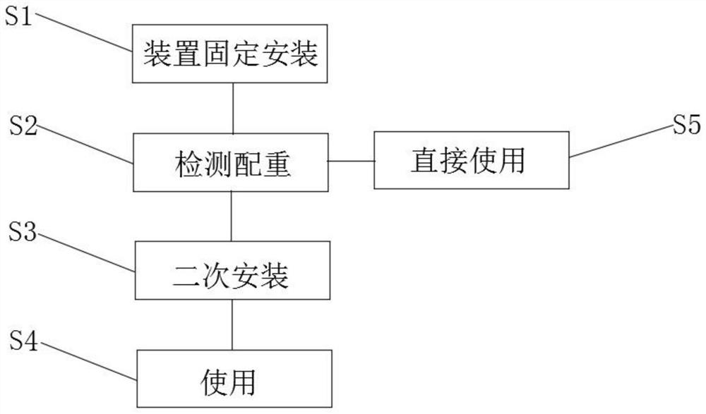
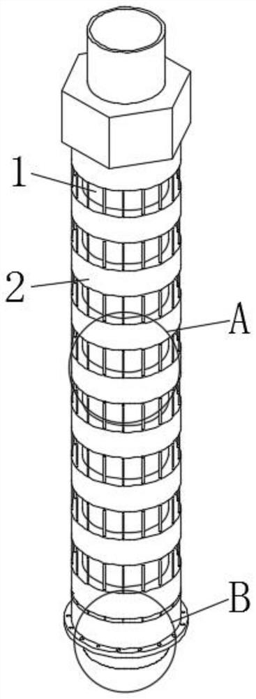
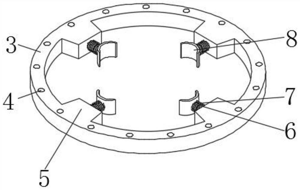
[0030] see Figure 1-5 , a method for reducing fuel pressure fluctuations in the high-pressure fuel pipe of an EFI diesel engine, including the following process: S1, fixed installation of the device: the shock-absorbing mechanism 2 is socketed outside the high-pressure fuel pipe body 1 through its own specific installation method, and the shock-absorbing mechanism 2. It consists of a fixed frame 3, a through hole 4, a fixed block 5, a cylinder 6, a spring 7, a block 8, a fixed seat 9, a mounting hole 10, a fixed rod 11, and a spacer sleeve 12. The fixed seat 9 is located on the high-pressure oil pipe body 1, and fixedly clamped with the high-pressure oil pipe body 1, one of the fixed bases 9 is fixedly connected with several fixed rods 11, the fixed rods 11 are far away from the center position of the fixed base 9, and several fixed rods 11 are clamped The fixed frame 3, the spacer bushing 12 is installed between two adjacent fixed frames 3, the spacer bushing 12 is fixedly c...

Embodiment 2

[0036] Based on Example 1, such as Figure 1-5 , the fixed base 9 is provided with several installation holes 10, and the installation holes 10.

[0037] Working principle: When using this kind of device, one of the fixing seats 9 with the fixing rod 11 is clamped on the high-pressure oil pipe body 1 first, and then the fixing frame 3 or the spacer bushing are selected according to the model and power of the diesel engine itself. 12, if the power of the diesel engine is large, then more fixed mounts 3 can be placed, otherwise, more spacer sleeves 12 can be placed. There will be a spacer sleeve 12, which can be placed repeatedly between the fixed frame 3 and the fixed frame 3. When placing the fixed frame 3 and the spacer sleeve 12, the through hole 4 on the fixed frame 3 is sleeved on the fixed rod 11 Above, the spacer sleeve 12 can be directly socketed on the fixed rod 11. After being placed, another fixed seat 9 is socketed on the high-pressure oil pipe body 1, and the fixe...


PUM


Abstract

The present invention relates to the technical field of high-pressure oil pipes of diesel engines, and discloses a method for reducing fuel pressure fluctuations in high-pressure oil pipes of electric fuel injection diesel engines, including the following process: S1, device fixed installation: the shock absorbing mechanism is socketed through its own specific installation method on the outside of the high-pressure oil pipe body; S2, detection counterweight: when the corresponding structure is installed, perform device performance detection; S3, secondary installation: when the weight is detected to be inappropriate, change the number of individuals in the shock absorbing mechanism again, S4, Use: after the secondary installation is proper, the device can be used; S5, direct use: when the counterweight is checked, it is detected that the weight of the installed shock absorbing mechanism is suitable, and the device can be used directly. This method for reducing fuel pressure fluctuations in the high-pressure fuel pipe of an EFI diesel engine is used to weaken the fluctuations generated by the high-pressure fuel pipe itself, thereby achieving the function of protecting the high-pressure fuel pipe body. It is relatively simple to install and disassemble.

Description

technical field [0001] The invention relates to the technical field of high-pressure oil pipes of diesel engines, in particular to a method for reducing fuel pressure fluctuations in the high-pressure oil pipes of electronic injection diesel engines. Background technique [0002] The most important use of diesel is in diesel engines for vehicles and ships. Compared with gasoline, diesel has high energy density and low fuel consumption. Diesel has low energy consumption, so some small cars and even high-performance cars have switched to diesel. [0003] Due to the high density of diesel itself, under normal circumstances, the part of diesel used is less, and most of the energy is lost in other forms. When the diesel engine is working, the fuel injector injects fuel, and the pressure is high, which makes the high-pressure oil pipe in the fuel delivery produce high-frequency vibration, and the oil pipe will bear a large oil pressure, which is an important factor that causes d...

Claims


Application Information

Patent Timeline
Patent Type & Authority Patents(China)
IPC IPC(8): F02M37/00
CPCF02M55/04
Inventor 石庆国周学升郭微微王守宝
Owner SHANDONG JIAOTONG UNIV
Why Eureka
Try Eureka