
An automatic pressure-regulating gravel cleaning system

An automatic pressure-regulating, stone-breaking technology, applied in the field of medical devices, can solve the problems of cumbersome operation and slow response speed

Active Publication Date: 2021-04-20
SUN YAT SEN MEMORIAL HOSPITAL SUN YAT SEN UNIV
View PDF13 Cites 0 Cited by
  • Summary
  • Abstract
  • Description
  • Claims
  • Application Information

AI Technical Summary

Problems solved by technology

In the existing stone clearing system at any time, when the doctor finds the pressure changes, he needs to artificially adjust the inflow or outflow flow, so as to indirectly adjust the pressure in the kidney, not only the response speed is slow, but also the operation is cumbersome

Method used


Image

  • An automatic pressure-regulating gravel cleaning system
  • An automatic pressure-regulating gravel cleaning system
  • An automatic pressure-regulating gravel cleaning system

Examples


Embodiment 1

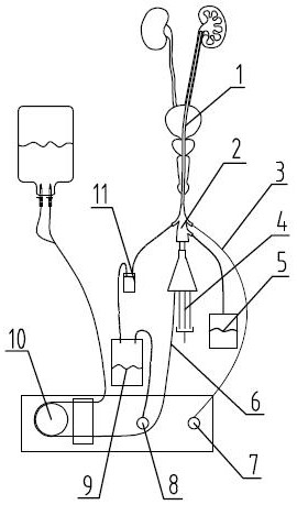
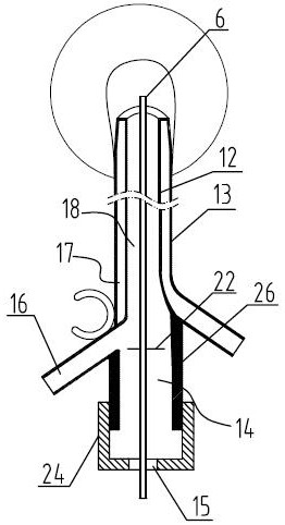
[0032] Such as figure 1 and figure 2 As shown, an automatic pressure-regulating gravel removal system includes an electronic mirror 4 and a mirror sheath, and the electronic mirror 4 includes a liquid inlet channel 6 . The mirror sheath includes a sheath body 2 and a sheath tube 1 , the sheath tube 1 is provided with a drainage channel 18 , and the sheath body 2 is provided with a transition chamber 14 communicating with the drainage channel 18 . The sheath 2 is made of transparent material, and the sheath 2 is provided with a marking line 22 . Specifically, the sheath body 2 includes a main body 26 and a cover plate 24 . The cover plate 24 is located at an end of the main body 26 away from the sheath tube 2 . The main body 26 and the cover plate 24 together form the transition chamber 14 .

[0033] Such as figure 1 and figure 2 As shown, the sheath body 2 is provided with a liquid discharge port 16 and a pressure regulating port 15 communicating with the transition cham...

Embodiment 2

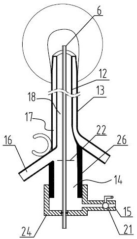
[0037] Such as image 3 As shown, compared with Embodiment 1, the difference of this embodiment is that: the sheath body 2 is also provided with an operation channel corresponding to the electronic mirror 4, and the electronic mirror 4 passes through the operation channel and communicates with the electronic mirror 4. The operating channel is slidingly sealed. The pressure regulating port 15 is set independently from the operating channel, and the pressure regulating port 15 is connected with the open liquid collection device 5. When the transition chamber 14 is filled with waste liquid and cannot be discharged in time or the liquid discharge port 16 is blocked, some The waste liquid can enter the liquid collection device 5 through the pressure regulating port 15 for temporary collection. The pressure regulating port 15 is provided with a switch 21 for controlling the opening amount of the pressure regulating port 15, and the flow rate can be changed by adjusting the opening ...

Embodiment 3

[0039] Such as Figure 4 As shown, compared with the second embodiment, the difference of this embodiment is that the pressure regulating port 15 is not provided on the cover plate 24, the sheath body 2 is provided with a confluence pipe 23, and the Both the liquid discharge port 16 and the pressure regulating port 15 communicate with the transition chamber 14 through the confluence pipe 23. With the change of the opening amount of the switch 21, the change of the liquid inlet flow rate and the liquid discharge flow rate is more sensitive, and the adjustment range is better.


PUM


Abstract

The invention relates to a medical device, and specifically discloses an automatic pressure-regulating type crushing stone cleaning system. The lithotripsy system includes an electronic mirror and a mirror sheath. The mirror sheath includes a sheath body and a sheath tube. The sheath tube is provided with a drainage channel, and the sheath body is provided with a transition to communicate with the drainage channel. chamber; the sheath body is provided with a discharge port and a pressure regulating port communicated with the transition chamber; it also includes a renal pressure monitoring module, which includes a pressure measuring tube and a hydraulic pressure detection tube communicated with the pressure measuring tube device, a regulating valve is provided between the hydraulic detection device and the pressure measuring tube, and a liquid filling channel is provided on the regulating valve, and the pressure measuring tube passes through the regulating valve, the hydraulic detection device and the liquid adding channel to select one connected. The above-mentioned crushed stone clearing system automatically balances the pressure in the kidney through the pressure regulating port, reduces the fluctuation of the pressure in the kidney, improves the safety of the operation, and simplifies the operation procedure.

Description

technical field [0001] The invention relates to a medical device, in particular to an automatic pressure-regulating type gravel-clearing system. Background technique [0002] Endovascular treatment is the main form of kidney stone treatment at present. The specific operation method is to enter the kidney through the urethra or body opening with an endoscope, and use laser to crush the kidney stones. The form of endovascular treatment is widely used due to its advantages of minimally invasive or non-invasive, and little harm to the body. [0003] During the operation, in order to ensure that the endoscope has a good intrarenal surgical field of view and facilitate the doctor to observe the situation in the kidney and the effect of the operation, the endoscope is usually used to build a liquid inlet channel for the passage of normal saline to prop up the kidney. Inner space, and at the same time build a waste liquid discharge channel, timely discharge the rubble generated by ...

Claims


Application Information

Patent Timeline
Patent Type & Authority Patents(China)
IPC IPC(8): A61B18/26
CPCA61B18/26A61B2018/00511A61B2018/00773A61B2018/00982A61B2218/007
Inventor 许可慰姚拥军洪启龙方潇姚彤周明
Owner SUN YAT SEN MEMORIAL HOSPITAL SUN YAT SEN UNIV
Learn More