Liquid distribution pipeline assembly and heat exchange device

A technology of heat exchange device and liquid distribution tube, which is applied in the direction of fixing catheter components, tubular elements, heat exchanger types, etc., which can solve the uneven flow rate of fluid, the inability to ensure uniformity, and reduce the uniformity of liquid distribution of liquid distribution pipeline components and other issues to achieve the effect of improving uniformity

Pending Publication Date: 2020-11-10
ZHEJIANG DUNAN THERMAL SCI & TECH
View PDF0 Cites 0 Cited by
  • Summary
  • Abstract
  • Description
  • Claims
  • Application Information

AI Technical Summary

Problems solved by technology

The liquid separation effect of the existing liquid distribution pipeline components is not ideal. After the fluid enters the manifold through the liquid separation channel from the liquid separation chamber, mixed flow will occur in the manifold, and the fluids located in different areas in the manifold Mixed with each other, so its flow trajectory is chaotic and disorderly, resulting in uneven flow velocity of the fluid in the manifold; in addition, because the fluid will be resisted by the inner wall of the liquid separation chamber, the flow velocity

Method used


Image

  • Liquid distribution pipeline assembly and heat exchange device
  • Liquid distribution pipeline assembly and heat exchange device
  • Liquid distribution pipeline assembly and heat exchange device

Examples


Embodiment Construction

[0051] The technical solutions in the embodiments of the present invention will be clearly and completely described below in conjunction with the accompanying drawings in the embodiments of the present invention. Obviously, the described embodiments are only part of the embodiments of the present invention, not all of them. Based on the implementation manners in the present invention, all other implementation manners obtained by persons of ordinary skill in the art without making creative efforts belong to the scope of protection of the present invention.

[0052] Unless otherwise defined, all technical and scientific terms used herein have the same meaning as commonly understood by one of ordinary skill in the technical field of the invention. The terminology used herein in the description of the present invention is only for the purpose of describing specific embodiments, and is not intended to limit the present invention. As used herein, the term "or / and" includes any and a...


PUM


Abstract

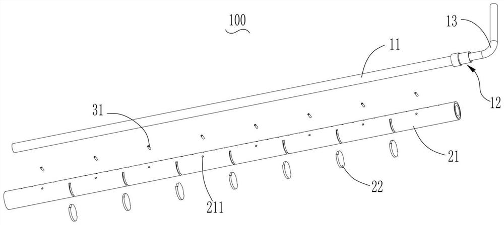
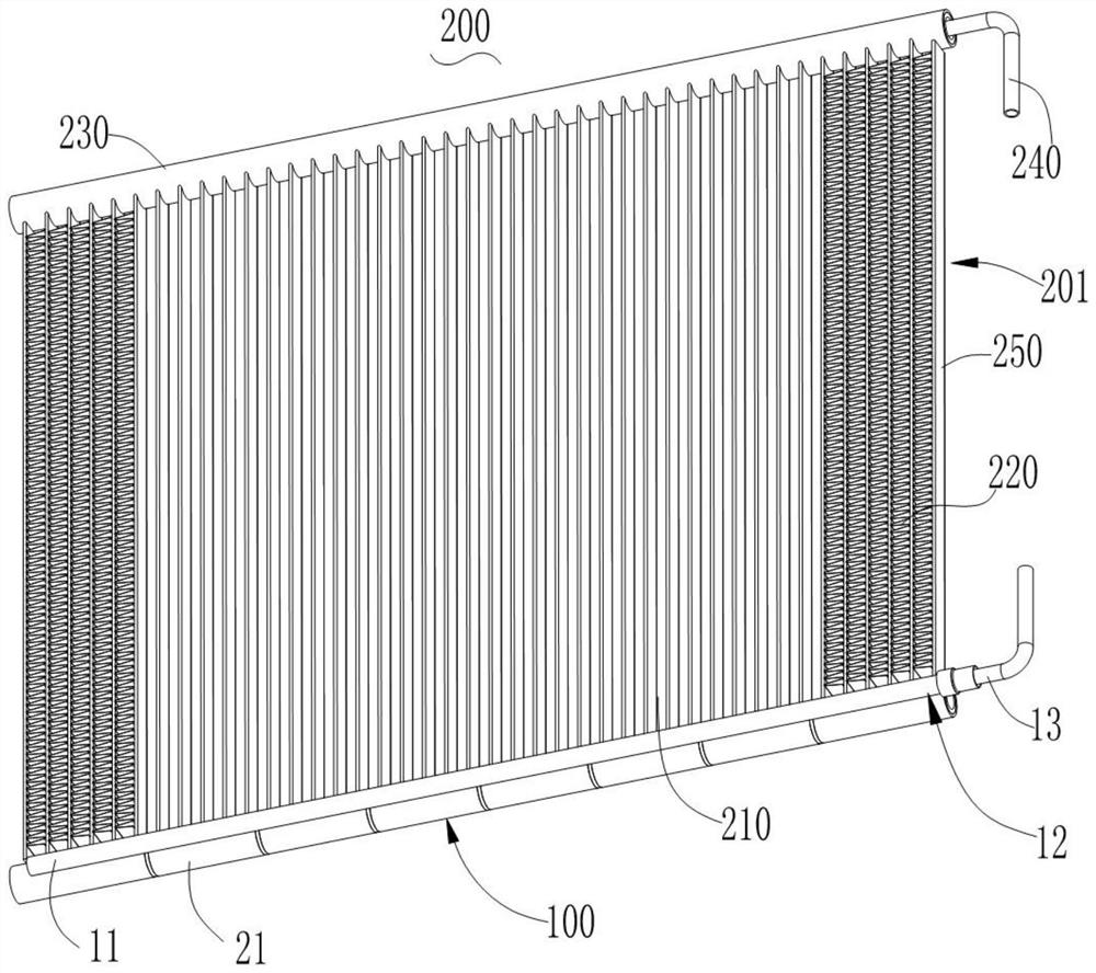
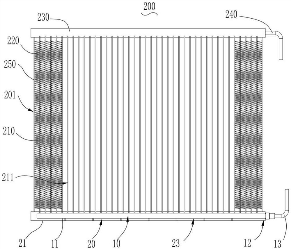
The invention provides a liquid distribution pipeline assembly and a heat exchange device. A liquid distribution chamber, a flow collecting chamber, and a liquid distribution channel are formed insidethe liquid distribution pipeline assembly. The liquid distribution channel is used for communicating the liquid distribution chamber with the flow collecting chamber, and enables fluid in the liquiddistribution chamber to flow into a flat pipe chamber through the flow collecting chamber. At least one blocking element is arranged in the flow collecting chamber. The blocking elements divide the flow collecting chamber into a plurality of flow collecting chambers, and each of the flow collecting chambers corresponds to multiple flat pipes. According to the invention, the flow collecting chamberis divided into a plurality of flow collecting chambers which are spaced from one another through the blocking elements, so that the phenomenon of secondary mixed flow or turbulent flow of fluid in different areas in the flow collecting chamber is eliminated, and mutual interference between the fluid at different positions in the flow collecting chamber is prevented; therefore, the problem of non-uniform flow velocity when the fluid flows to the liquid using device from different positions in the flow collecting chamber is solved, each flow collecting chamber can uniformly collect the fluid from the liquid distributing chamber and uniformly supply the fluid to the liquid using device, and the uniformity of liquid distribution of the fluid by the liquid distributing pipeline assembly is improved.

Description

technical field [0001] The invention relates to the technical field of fluid control, in particular to a liquid distribution pipeline assembly and a heat exchange device. Background technique [0002] The liquid distribution pipeline assembly is a device that divides the concentrated inflow of fluid to form multiple fluid branches. It can transport the fluids of multiple branches to the liquid device respectively. There are liquid separation chambers for receiving fluids inside. The collecting chamber for connecting the liquid-using device, and the liquid-distributing channel for connecting the liquid-distributing chamber and the collecting chamber. The liquid separation effect of the existing liquid distribution pipeline components is not ideal. After the fluid enters the manifold through the liquid separation channel from the liquid separation chamber, mixed flow will occur in the manifold, and the fluids located in different areas in the manifold Mixed with each other, s...

Claims


Application Information

Patent Timeline
IPC IPC(8): F28F9/22F28D1/053F28F1/34
CPCF28D1/05383F28F1/34F28F9/22F28F2009/222
Inventor 魏文建梁新宇
Owner ZHEJIANG DUNAN THERMAL SCI & TECH
Why Eureka
Try Eureka