Antenna array direction finding method and device and electronic equipment

An antenna array and direction finding technology, which is applied in the field of direction finding, can solve the problems of small-diameter antenna array direction finding performance degradation, direction finding antenna aperture constraints, etc., and achieve miniaturization, improve direction finding accuracy, and ensure direction finding accuracy Effect

Pending Publication Date: 2020-11-10
36TH RES INST OF CETC
View PDF3 Cites 2 Cited by
  • Summary
  • Abstract
  • Description
  • Claims
  • Application Information

AI Technical Summary

Problems solved by technology

[0003] However, due to the limitation of the installation platform, the caliber that can be installed with the direction-finding antenna of the interferometer will inevitably be restricted.
However, the direction-finding performance of the small-aperture antenna array used by traditional interferometers is greatly reduced. Therefore, how to break through the direction-finding mechanism and constraints of the small-aperture antenna array to improve the direction-finding performance of the small-aperture antenna array is a technical problem that needs to be solved urgently.

Method used


Image

  • Antenna array direction finding method and device and electronic equipment
  • Antenna array direction finding method and device and electronic equipment
  • Antenna array direction finding method and device and electronic equipment

Examples


Embodiment Construction

[0036] Exemplary embodiments of the present application will be described in more detail below with reference to the accompanying drawings. Although exemplary embodiments of the present application are shown in the drawings, it should be understood that the present application may be embodied in various forms and should not be limited to the embodiments set forth herein. Rather, these embodiments are provided so that the present application can be more thoroughly understood, and the scope of the present application can be fully conveyed to those skilled in the art.

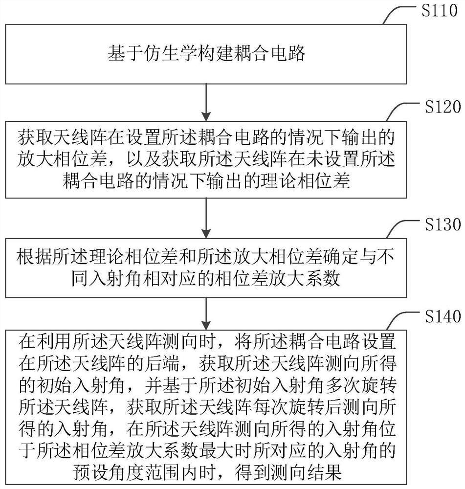
[0037] figure 1 A schematic flow diagram showing a method for finding the direction of an antenna array according to an embodiment of the present application, see figure 1 , the antenna array direction finding method of the embodiment of the present application includes the following steps S110 to S140:

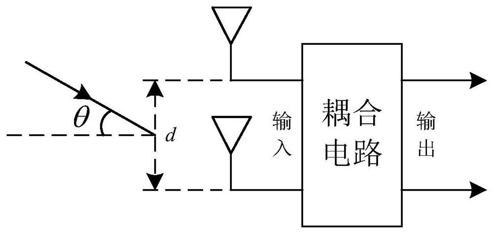
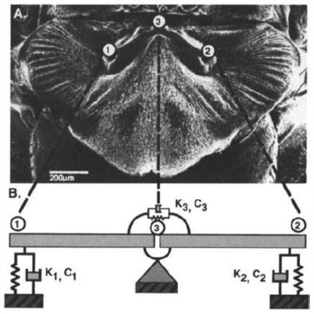
[0038] Step S110, constructing a coupling circuit based on bionics.

[0039] The idea of ​​bionics in the p...


PUM


Abstract

The invention discloses an antenna array direction finding method and device and electronic equipment. The method comprises the following steps: constructing a coupling circuit based on bionics; obtaining an amplification phase difference output by an antenna array under the condition that the coupling circuit is arranged and a theoretical phase difference output under the condition that the coupling circuit is not arranged; determining phase difference amplification coefficients corresponding to different incident angles according to the theoretical phase difference and the amplification phase difference; when the antenna array is used for direction finding, the coupling circuit is arranged at the rear end of the antenna array, acquiring an initial incident angle obtained through direction finding of the antenna array, rotating the antenna array multiple times based on the initial incident angle to acquire an incident angle obtained through direction finding after each time of rotation of the antenna array; and when the incident angle obtained by direction finding of the antenna array is within the preset angle range of the corresponding incident angle when the phase difference amplification coefficient is maximum, obtaining a direction finding result. According to the embodiment of the invention, the miniaturization of the direction-finding antenna array can be realized whilethe direction-finding precision is ensured, and the antenna array is better suitable for a miniaturized platform.

Description

technical field [0001] The present application relates to the technical field of direction finding, and in particular to an antenna array direction finding method, device and electronic equipment. Background technique [0002] At present, the commonly used direction finding equipment mostly adopts the interferometer direction finding system, and its direction finding accuracy is directly proportional to the diameter of the direction finding antenna array. antenna array. [0003] However, due to the limitation of the installation platform, the aperture that can be installed with the direction-finding antenna of the interferometer is bound to be restricted. However, the direction-finding performance of the small-aperture antenna array used by traditional interferometers is greatly reduced. Therefore, how to break through the direction-finding mechanism and constraints of the small-aperture antenna array to improve the direction-finding performance of the small-aperture antenn...

Claims


Application Information

Patent Timeline
Patent Type & Authority Applications(China)
IPC IPC(8): G06F30/367G06F30/17
CPCG06F30/367G06F30/17
Inventor 黄凯尤明懿叶云霞
Owner 36TH RES INST OF CETC
Why Eureka
Try Eureka