Measuring system and measuring method for determining wear of brake lining of friction brake

A technology of friction brakes and measurement systems, applied in the direction of brake types, mechanical equipment, etc., can solve problems such as reduced service life, and achieve the effect of low cost and subsequent cost reduction

Active Publication Date: 2020-11-10
KNORR BREMSE SYST FUR SCHIENENFAHRZEUGE GMBH
View PDF16 Cites 1 Cited by
  • Summary
  • Abstract
  • Description
  • Claims
  • Application Information

AI Technical Summary

Problems solved by technology

As a result, its service life will be reduced

Method used


Image

  • Measuring system and measuring method for determining wear of brake lining of friction brake
  • Measuring system and measuring method for determining wear of brake lining of friction brake
  • Measuring system and measuring method for determining wear of brake lining of friction brake

Examples


Embodiment Construction

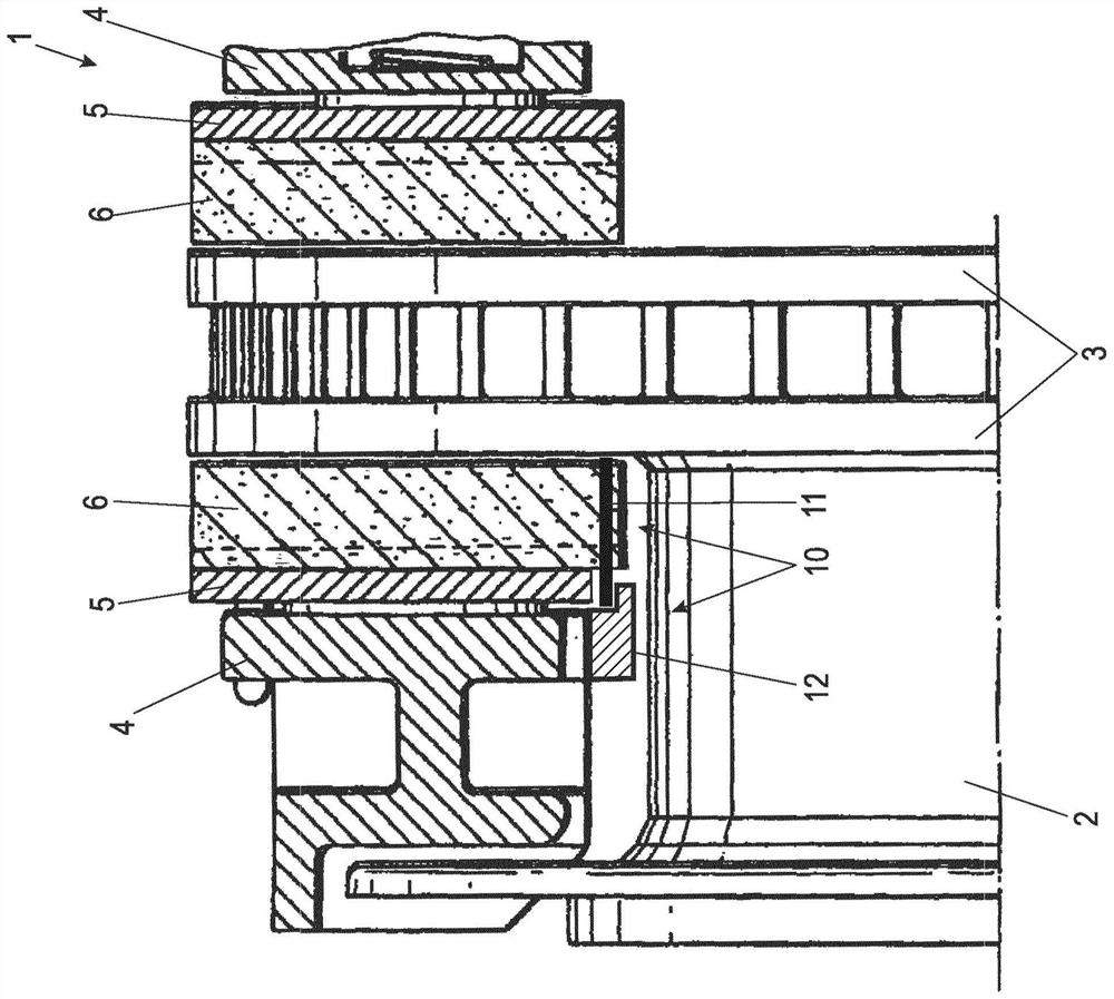
[0032] exist figure 1 The middle section again shows a part of the friction brake 1 of a rail vehicle, for example a freight car.

[0033] The friction brake 1 is a disc brake in which a brake disc 3 , here an internally ventilated disc, is fastened on a hub 2 of the vehicle. There is a pressing mechanism 4 , not further shown here, which acts on two brake linings 6 , which are each supported by a lining carrier 5 . The pressing mechanism 4 is not shown in detail here. The pressing mechanism can be actuated pneumatically, hydraulically or electrically in a known manner. When the friction brake 1 is actuated, the brake lining 6 is pressed against the brake disk 3 by the pressing mechanism 4 and thus brought into frictional engagement with the brake disk 3 .

[0034] As the brake is used, not only the brake disc 3 but also the brake lining 6 wears out in that the lining thickness (lining thickness) decreases. In order to avoid a direct frictional contact of the brake lining ...


PUM


Abstract

The invention relates to a measuring system for determining the wear of a brake lining (6) of a friction brake, wherein a wear element (11) is integrated into the brake lining (6), the wear of which wear element is determined to represent the brake lining (6) or by means of which wear of the brake lining (6) is detected. The wear element (11) is ferromagnetic and the measuring system has a permanent magnet (13) and a magnetic field sensor which are arranged such that the wear element (11) lies in the field of the permanent magnet (13), and the magnetic field sensor detects a magnetic field intensity influenced by the wear of the wear element (11) or the brake lining (6).

Description

technical field [0001] The invention relates to a measuring system and a measuring method for determining the wear of a brake lining of a friction brake, wherein wear elements are integrated into the brake lining, the wear of which is determined to represent the brake lining noodle. [0002] The measuring system and the measuring method for wear determination can detect the attainment of the wear limit of the brake lining during operation of the vehicle and can indicate a necessary replacement of the brake lining. In this way, the length of the inspection intervals in which a visual inspection of the lining thickness is carried out can be extended, whereby the outlay for inspections and subsequent costs due to increased downtimes can be reduced. Background technique [0003] A device is known, for example, from DE 10 2006 042 777 B3, in which the adjusting spindle of the pressing device of the brake is coupled to the sensor via a reduction gear. The sensor, which interacts...

Claims


Application Information

Patent Timeline
Patent Type & Authority Applications(China)
IPC IPC(8): F16D66/02
CPCF16D66/026F16D66/027F16D66/028
Inventor M-G·埃尔斯托尔普夫S·库斯F·黑尔默O·帕拉斯卡H·比拉尔M·迪特里希
Owner KNORR BREMSE SYST FUR SCHIENENFAHRZEUGE GMBH
Why Eureka
Try Eureka