
Processing method and processing tool for trough plate

A processing method and groove plate technology, applied in the direction of manufacturing tools, metal processing equipment, metal processing machinery parts, etc., can solve the problems of reducing buffer groove efficiency, complicated operation steps, etc., to improve the punching efficiency, avoid vibration loosening, reduce The effect of the replacement process

Active Publication Date: 2020-11-13
合肥陶陶新材料科技有限公司
View PDF12 Cites 3 Cited by
  • Summary
  • Abstract
  • Description
  • Claims
  • Application Information

AI Technical Summary

Problems solved by technology

[0004] The object of the present invention is to provide a groove plate processing method and a cutting tool for processing, which solves the problem that different cutter heads need to be replaced according to different types of grooves. Calibration work, complicated operation steps, and technical problems that reduce the efficiency of the buffer tank

Method used


Image

  • Processing method and processing tool for trough plate
  • Processing method and processing tool for trough plate
  • Processing method and processing tool for trough plate

Examples


Embodiment approach

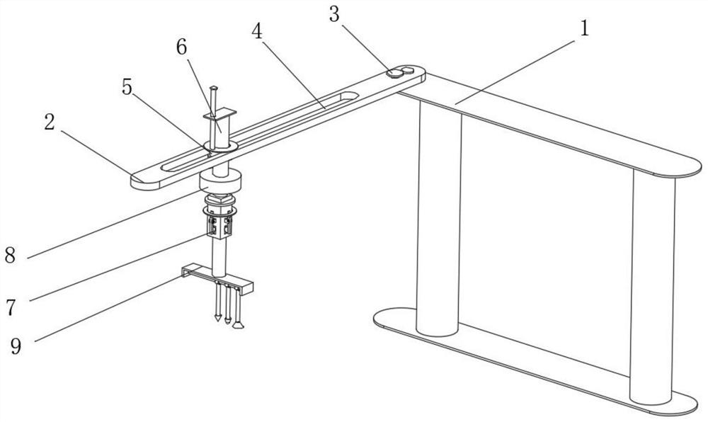
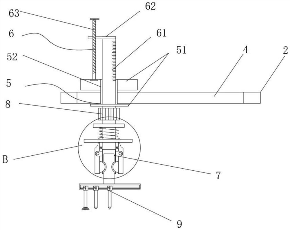
[0043] As an embodiment of the present invention, the depth positioning assembly 6 includes a telescopic rod 61, a positioning plate 62 and a screw rod 63, the telescopic rod 61 is penetrated inside the sliding sleeve 52, and the positioning plate 62 is welded on the top of the telescopic rod 61 , The inside of the positioning plate 62 is provided with a screw hole, the telescopic rod 61 fits through the screw hole, and the bottom end of the screw mandrel 63 is mounted on the top side of the limiting plate 51 through a bearing.

[0044] As an embodiment of the present invention, the motor 8 is mounted on the bottom end of the telescopic rod 61 through bolts, and the circumferential surface of the telescopic rod 61 is provided with scale marks.

[0045] As an embodiment of the present invention, the clamping assembly 7 includes a positioning cylinder 71, a contraction spring 72, a return spring 73, a movable cylinder 74, a swing rod 75, a bearing 76, a positioning block 77 and a...


PUM


Abstract

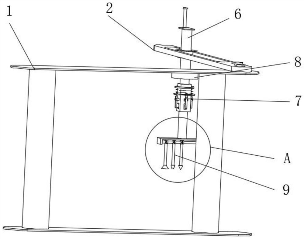
The invention discloses a processing method and a processing tool for a trough plate. The processing tool comprises a support seat, a swing plate, a positioning pin, a sliding hole, a motor and a rotating assembly, wherein the swing plate is in fit installation on the top side of the support seat through a pin, the sliding hole is formed in the swing plate, a cutter head is adjusted to a central position of a rotating frame by setting the rotating assembly and releasing a positioning screw rod on a roller, so the used cutter head is free to sag and position and the unused cutter head and the used cutter head are arranged vertically; the roller is positioned by the positioning screw rod so as to replace the cutter head randomly, and the conversion of various cutter heads can be realized; the tool replacement process can be reduced, and the efficiency of punching is improved; by setting a clamping assembly, a movable cylinder is squeezed when the tool is replaced, the swing rod is resetunder the cooperation of a contraction spring, and a positioning block is clamped in the positioning hole to realize replacement; and the stability of the replaced cutter head can be ensured, vibration and loosening are avoided, and the stability and safety of a punching process are ensured.

Description

technical field [0001] The invention relates to the field of groove plate processing, in particular to a groove plate processing method and a tool for processing. Background technique [0002] Groove board refers to a board with T-shaped V-shaped or U-shaped grooves on the surface of MDF or other boards to form decorative stripes or fixed pendants; [0003] When slotting the slot plate, different cutter heads need to be replaced according to different types of slots. When the cutter head is replaced, it needs a long time of downtime. After restarting, it needs to be calibrated. The operation steps are complicated and the buffer is reduced. Groove efficiency. When fixing the tool, it is generally fixed by screws. During the vibration operation, it is easy to loosen, affecting the stability of the tool, and the safety is low. When punching the plate groove, the depth of the groove cannot be accurately grasped. , the accuracy of the slot is not easy to grasp. Contents of the...

Claims


Application Information

Patent Timeline
Patent Type & Authority Applications(China)
IPC IPC(8): B23P15/00B23C3/28B23Q3/155B23Q5/34
CPCB23C3/28B23P15/00B23Q3/15506B23Q5/34
Inventor 杨盛国曹树龙唐占银周阳陈思
Owner 合肥陶陶新材料科技有限公司
Learn More