Mobile contact line supporting device and mobile contact network system

A technology of support device and catenary, applied in the direction of overhead lines, etc., can solve the problems of life influence at the hinge shaft of the cantilever, the moment at the hinge shaft cannot be improved, etc., and achieve the effect of large balancing moment and reducing power

Inactive Publication Date: 2020-11-13
智慧支点(北京)科技有限公司
View PDF6 Cites 0 Cited by
  • Summary
  • Abstract
  • Description
  • Claims
  • Application Information

AI Technical Summary

Problems solved by technology

With this cantilever structure, the bending moment generated by the gravity of the cantilever and the contact line on the hinge shaft is all borne by the hinge bearing, which has a great influence on the life of the cantilever hinge shaft
In some improvements, the movement of the cantilever can be changed to turn up and down. When the angle between the cantilever and the column becomes smaller, the force of gravity on the hinge axis will decrease, so the moment will also decrease; but the angle between the cantilever and the column is smaller. When the value is large, the situation where the torque at the hinge shaft is large still cannot be improved

Method used


Image

  • Mobile contact line supporting device and mobile contact network system
  • Mobile contact line supporting device and mobile contact network system
  • Mobile contact line supporting device and mobile contact network system

Examples


Embodiment Construction

[0025] In order to more clearly understand the above objects, features and advantages of the present disclosure, the solutions of the present disclosure will be further described below. It should be noted that, in the case of no conflict, the embodiments of the present disclosure and the features in the embodiments can be combined with each other.

[0026] In the following description, many specific details are set forth in order to fully understand the present disclosure, but the present disclosure can also be implemented in other ways than described here; obviously, the embodiments in the description are only some of the embodiments of the present disclosure, and Not all examples.

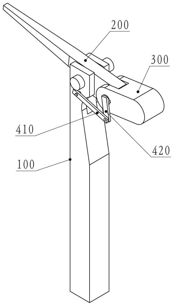
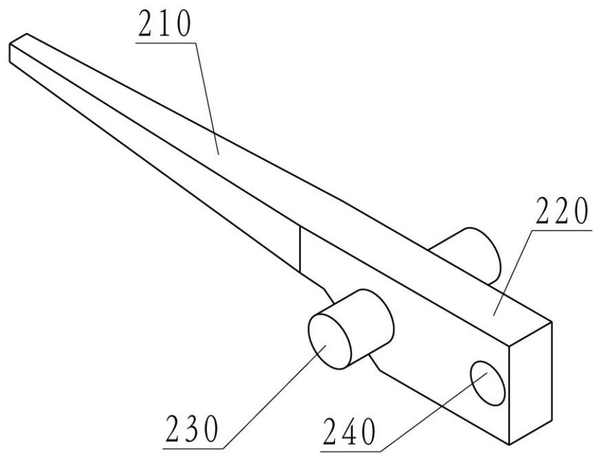
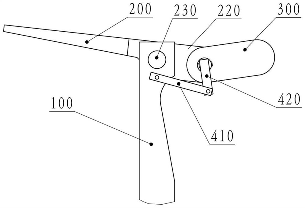
[0027] The mobile catenary support device provided by the present disclosure is arranged on a column in a catenary system, and is used for connecting and driving a catenary line. The mobile catenary supporting device includes a cantilever, a power unit, a counterweight and a counterweight drivin...


PUM


Abstract

The invention relates to a mobile contact network supporting device and a mobile contact network system, and the mobile contact network supporting device is arranged on a stand column in the contact network system and comprises a cantilever, a power device, a balance weight and a balance weight driving device. The cantilever comprises a contact line connecting section, a balance weight connectingsection and a hinge structure between the contact line connecting section and the balance weight connecting section and is hinged to the stand column through the hinge structure, the contact line connecting section extends out of one side of the stand column, and the balance weight connecting section is located on the other side of the stand column; the power device is arranged on the stand columnand can drive the cantilever to rotate relative to the stand column; the balance weight is movably arranged on the balance weight connecting section of the cantilever, and the distance between the gravity center of the balance weight and the stand column changes when the balance weight moves relative to the cantilever; the balance weight driving device is used for driving the balance weight to move relative to the cantilever. The balance weight driving device can enable the angle between the balance weight and the cantilever to be adjustable, larger balance torque can be provided, and power needed when the cantilever rotates is reduced.

Description

technical field [0001] The present disclosure relates to the field of moving catenary technology, and in particular to a moving catenary support device and a moving catenary system. Background technique [0002] The mobile catenary can be applied to the freight yard in the electrified railway transportation system, which can eliminate the operation of the diesel locomotive pulling the electric locomotive into and out of the yard. In the mobile catenary, it is necessary to set up multiple columns along the track of the freight station, and the supporting device for supporting the catenary cable and the contact line needs to be installed on the column. The supporting device should be able to move actively or passively so that the connected catenary cable and contact line The contact line is moved from above the track to one side. A Chinese patent application "CN101306652A-Horizontal Rotating Rigid Movable Catenary System" discloses a movable catenary system, the supporting de...

Claims


Application Information

Patent Timeline
Patent Type & Authority Applications(China)
IPC IPC(8): B60M1/20B60M1/13
CPCB60M1/13B60M1/20
Inventor 李蔚梁建华陈志
Owner 智慧支点(北京)科技有限公司
Why Eureka
Try Eureka