Eureka AIR delivers breakthrough ideas for toughest innovation challenges, trusted by R&D personnel around the world.

Polar region inertial navigation method based on virtual ball normal vector model

An inertial navigation and normal vector technology, which is applied in the field of polar area inertial navigation based on the virtual sphere normal vector model, and can solve the problems of complex calculation process, speed calculation error, and increased algorithm complexity.

Active Publication Date: 2020-11-13
NAT UNIV OF DEFENSE TECH
View PDF7 Cites 4 Cited by
  • Summary
  • Abstract
  • Description
  • Claims
  • Application Information

AI Technical Summary

Problems solved by technology

Using the abscissa system or the grid system for navigation calculation will produce a principle error under the spherical model, and the accuracy cannot be guaranteed. The calculation process of the radius of curvature in multiple directions is complicated under the ellipsoid model; The radius of curvature at the pole is also difficult to obtain accurately due to the convergence of meridians. There are errors in the calculation of attitude and velocity in the polar area. When the inertial navigation itself has position errors, the resulting errors will be more significant.
[0005] The grid coordinate system navigation method does not work properly near the equator, and the abscissa algorithm creates new poles at the equator, so neither is capable of global navigation
In addition, the navigation methods of the grid coordinate system and the abscissa coordinate system cannot use a unified global error model to analyze their error characteristics. Brings changes in the integration process. For the damping algorithm and the combined navigation filtering algorithm, the switching process will affect the continuity and consistency of the internal algorithm, and also greatly increase the complexity of the algorithm.

Method used

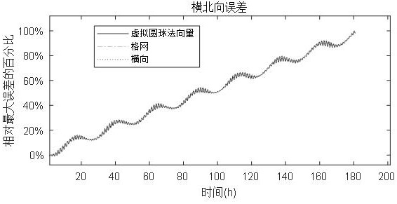
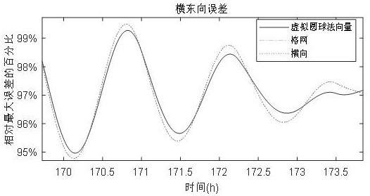
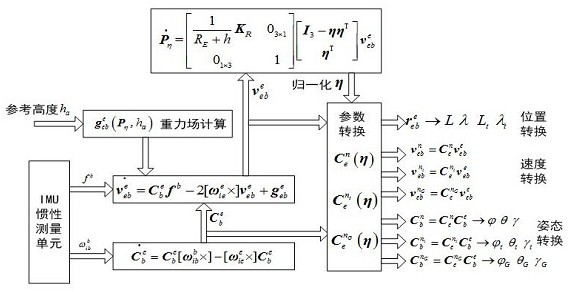

Image

  • Polar region inertial navigation method based on virtual ball normal vector model
  • Polar region inertial navigation method based on virtual ball normal vector model
  • Polar region inertial navigation method based on virtual ball normal vector model

Examples


Embodiment Construction

[0056] In order to make the purpose, technical solutions and advantages of the embodiments of the present invention clearer, the spirit of the disclosure of the present invention will be clearly described below with the accompanying drawings and detailed descriptions. Any person skilled in the art will understand the embodiments of the present invention. , when it can be changed and modified by the technology taught in the content of the present invention, it does not depart from the spirit and scope of the content of the present invention. The exemplary embodiments and descriptions of the present invention are used to explain the present invention, but not to limit the present invention.

[0057] refer to figure 1 , the present embodiment provides a polar region inertial navigation method based on a virtual spherical normal vector, including:

[0058] Step 1: Binding the initial navigation parameters, receiving the real-time rotational angular velocity and specific force ve...


PUM


Abstract

The invention relates to a polar region inertial navigation method based on a virtual ball normal vector model. The method comprises steps of initial navigation parameters being bound, and the real-time data information from an IMU inertial measurement unit and an altimeter being received; establishing a virtual ball normal vector model, and completing quaternion-based position representation andnavigation parameter conversion; establishing a differential equation based on the position, speed and attitude of the virtual ball normal vector model under the earth-centered earth-fixed coordinatesystem, and completing the calculation of navigation parameters according to the data information received in real time; and converting the navigation parameters under the earth-centered earth-fixed coordinate system into required navigation parameters under the coordinate system and outputting the required navigation parameters. The quadruple position representation method has global applicability, and avoids complex switching between a polar region and a non-polar region in a traditional scheme. The method only relates to accurate curvature radius calculation of the meridian circle and the mortise unitary circle in the reference ellipsoid model, an error problem caused by approximate curvature radius calculation under the reference ellipsoid model in a traditional method is avoided, andcalculation precision is improved.

Description

technical field [0001] The invention relates to the technical field of navigation, in particular to a polar area inertial navigation method based on a virtual spherical normal vector model. Background technique [0002] With the development of polar routes, polar navigation has become a research hotspot in recent years. Because inertial navigation has excellent autonomy and is not affected by geomagnetic changes and solar storms in polar regions, inertial navigation has become an important means of navigation in polar regions. [0003] The current traditional position representation method is to use latitude and longitude (horizontal longitude and horizontal latitude) elevation to represent the position. However, since all longitudes meet at the poles, the longitudes at the poles are not defined, and there is a singularity in the representation method of latitude and longitude positions. In addition, when the vehicle is close to the pole, this representation method will le...

Claims


Application Information

Patent Timeline
IPC IPC(8): G01C21/18
CPCG01C21/18
Inventor 吴文启刘潺冯国虎王茂松
Owner NAT UNIV OF DEFENSE TECH
Why Eureka
Eureka Blog
Learn More