
Charging elastic pin for Bluetooth earphone

A technology for charging pogo pins and bluetooth earphones, which is applied to earpiece/earphone accessories, rechargeable batteries/devices, circuits, etc. It can solve problems such as difficulty in guaranteeing machining accuracy, inability to energize the contact surface, and incomplete contact of charging contacts, etc., to achieve improved Connection stability, the effect of improving stability

Active Publication Date: 2020-11-13
东莞市燊瑞电子科技有限公司
View PDF13 Cites 0 Cited by
  • Summary
  • Abstract
  • Description
  • Claims
  • Application Information

AI Technical Summary

Problems solved by technology

However, when carrying the charging box out, the Bluetooth earphones placed in it tend to shift under frequent vibrations, resulting in incomplete contact of the charging contacts or poor contact affecting the charging effect
[0003] There are also some technical solutions in the prior art. For example, the Chinese patent with application number CN201621481659.4 includes a needle tube and a needle shaft. A spring is installed in the needle tube. A polygonal contact surface is provided on the contact end of the spring, and several chamfered connection surfaces are provided between the contact surface and the needle shaft. However, in actual use, although the polygonal contact surface increases the stability of the connector contact , but there is still the problem that the processing accuracy is difficult to guarantee. In fact, some contact surfaces cannot be energized due to the gap during installation.

Method used


Image

  • Charging elastic pin for Bluetooth earphone
  • Charging elastic pin for Bluetooth earphone

Examples


Embodiment approach

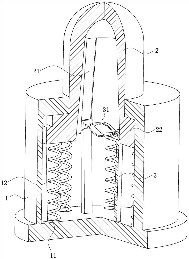
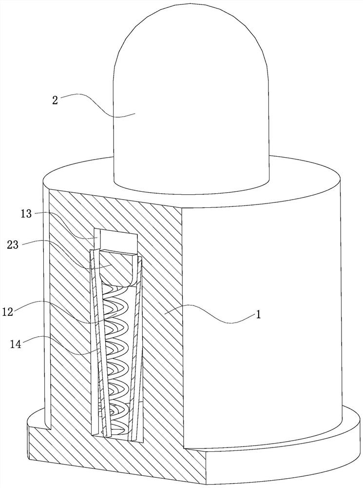
[0027] As an embodiment of the present invention, a clamping piece 14 is installed in the guide groove 13; there are two groups of the clamping pieces 14, two for each group, which are installed in two guide grooves 13 respectively; The two ends of the sheet 14 are respectively inserted into the side walls at both ends of the guide groove 13; the clamping sheet 14 is distributed in a V shape in the guide groove 13, and the V-shaped opening is in the same direction as the opening of the installation hole; the clamping sheet 14 exists elastic, and the length of the clamping piece 14 is greater than the length of the guide groove 13; the width of the guide rod 23 is equal to the width of the V-shaped opening of the clamping piece 14, which is greater than the width of the lower end of the clamping piece 14; Close contact between sheets 14;

[0028] When working, the needle shaft 2 is squeezed and moves toward the bottom of the mounting hole, the guide rod 23 installed on the need...


PUM


Abstract

The invention belongs to the technical field of Bluetooth earphones, and particularly relates to a charging elastic pin for a Bluetooth earphone. The charging elastic pin comprises a shell and a pinshaft. A mounting hole is formed in the shell. The pin shaft is mounted in a mounting hole in the shell. A contact ring is arranged at the lower end of the pin shaft. The contact ring is in contact with the inner wall of the mounting hole. A guide groove is formed in the side wall of the mounting hole. The number of the guide grooves is two. The guide grooves are symmetrically distributed in the inner wall of the mounting hole. A guide rod is mounted on the contact ring. The guide rod is perpendicular to the center line of the pin shaft. The number of the guide rods is two, and the two guide rods are symmetrically distributed on the contact ring. The guide rod can be inserted into the guide groove and can freely move in the guide groove. Springs are mounted in the mounting holes. The charging elastic pin is simple in structure, high in reliability and good in connection stability, and the outage risk in the connection process is avoided.

Description

technical field [0001] The invention belongs to the technical field of bluetooth earphones, in particular to a charging pin for bluetooth earphones. Background technique [0002] The Bluetooth headset needs to be charged after using it for a period of time. The Bluetooth headset charging box is a portable mobile power supply, which is very convenient to use. When charging, just put the Bluetooth headset into the corresponding headset slot. Good storage of Bluetooth headsets to avoid loss of Bluetooth headsets. However, when carrying the charging box out, the Bluetooth earphones placed in it tend to shift under frequent vibrations, resulting in incomplete contact of the charging contacts or poor contact affecting the charging effect. [0003] There are also some technical solutions in the prior art. For example, the Chinese patent with application number CN201621481659.4 includes a needle tube and a needle shaft. A spring is installed in the needle tube. A polygonal contact...

Claims


Application Information

Patent Timeline
IPC IPC(8): H01R13/04H01R13/17H01R13/502H01R13/629H04R1/10
CPCH01R13/04H01R13/17H01R13/502H01R13/629H04R1/1025
Inventor 梁静华梁其敏林玉寿吕平风
Owner 东莞市燊瑞电子科技有限公司
Learn More