

Linear laser light source and photographing equipment
A linear laser and light source technology, applied in the field of light source compensation, can solve the problems of poor lighting uniformity, large equipment volume, poor shooting effect, etc., and achieve the effects of easy maintenance, small size and simple operation.
- Summary
- Abstract
- Description
- Claims
- Application Information
AI Technical Summary
Problems solved by technology
Method used
Image

Examples
specific Embodiment approach 1
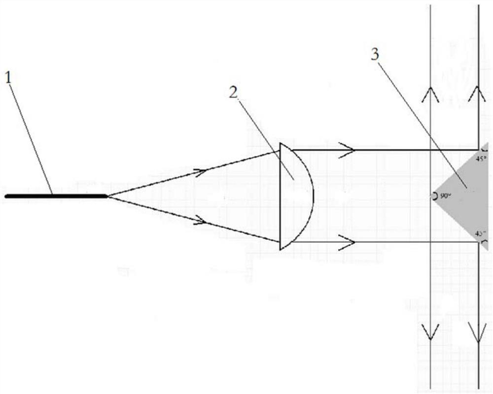
[0025] Specific implementation mode one: combine figure 1 Describe this embodiment, the linear laser light source described in this embodiment includes a laser 1, a collimator lens 2 and a conical reflector 3, and the laser 1, collimator lens 2 and conical reflector 3 are arranged at intervals in sequence, and the laser 1 The emitted laser light is collimated by the collimating lens 2 and converted into parallel light, which is then reflected by the conical mirror 3 and converted into 360° laser light;
[0026] In this specific embodiment, when in use, the light source is mainly composed of a fiber-coupled laser light source, a collimating lens 2 and a conical reflector 3. The light is emitted by the light source and becomes parallel light after being collimated by the collimating lens 2, and the parallel light The reflection of the mirror becomes a 360-degree line laser. By changing the shape of the conical mirror 3, the laser angle can be adjusted from 0 to 360 degrees. Thi...
specific Embodiment approach 2
[0027] Specific implementation mode two: combination figure 1 Describe this embodiment. This embodiment is a further limitation on the linear laser light source described in Embodiment 1. In the linear laser light source described in this embodiment, the conical reflector 3 is a conical reflector, and the The apex of the conical reflector 3 is arranged near the side of the collimator lens 2, the axis of the laser 1, the axis of the collimator lens 2 and the axis of the conical reflector are on the same straight line, the conical reflector The cross-section is an isosceles right triangle, and the apex angle of the conical reflector close to the collimating lens 2 is 90°.
specific Embodiment approach 3
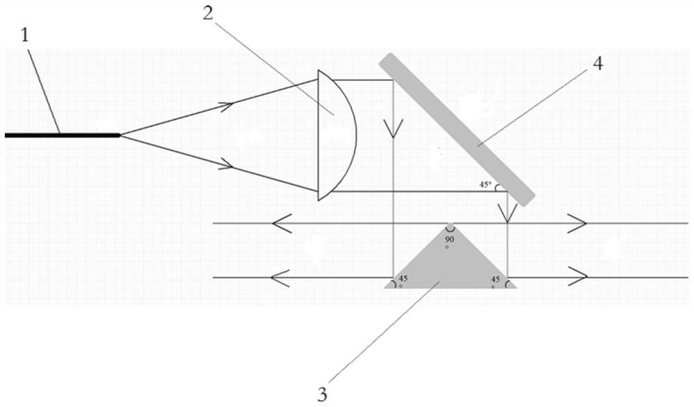
[0028] Specific implementation mode three: combination figure 2 Describe this embodiment. This embodiment is a further limitation on the linear laser light source described in the second specific embodiment. The linear laser light source described in this embodiment also includes a plane reflector 4, along the light Propagation direction, the plane reflector 4 is arranged between the collimator lens 2 and the conical reflector 3, the parallel light is first reflected by the plane reflector 4, and then passes through the cone after changing direction Shaped mirror 3 reflection, converted into 360 ° of laser light.
[0029] In this embodiment, the arrangement position and structure of the linear laser light source are more flexible by arranging the plane reflector 4 to adjust the direction of the laser light.
PUM
 Abstract
Description
Claims
Application Information