Air disinfection machine

An air sterilizer and fan technology, applied in air quality improvement, mechanical equipment, air flow control components, etc., can solve the problems of easy aging of plastic parts, uneven light intensity, sterilization dead angle affecting sterilization effect, etc., to improve the uniformity of light. , Improve the sterilization effect, eliminate the effect of lighting dead angle

Active Publication Date: 2021-06-04
NINGBO FOTILE KITCHEN WARE CO LTD
7 Cites 0 Cited by

AI-Extracted Technical Summary

Problems solved by technology

[0004] The above-mentioned existing light sterilization structure, the shell is generally made of plastic, under the long-term irradiation of ultraviol...

Method used

The central part of the top wall of the housing 1 of the present embodiment is provided with an upwardly extending air guide 13, the outer diameter of the air guide 13 gradually increases from bottom to top and the outer peripheral wall is shaped into an arc that gradually arches upwards Wind guiding surface 131. This structure is beneficial to spread and disperse the sterilized air quickly and evenly in the room.
[0026] There are four germicidal lamp tubes 22 in this embodiment and they are uniformly distributed along the circumference of the air guide channel 20, and the second reflective surface 262 is an arc-shaped surface corresponding to the germicidal lamp tube 22 arrangement. Specifically, the reflector assembly 26 includes four reflector plates 261 so that each germicidal lamp tube 22 corresponds to a reflecto...

Abstract

The invention relates to an air disinfection machine which comprises a shell and a sterilization lamp assembly arranged in the shell. An air inlet is formed in the lower portion of the shell, and an air outlet is formed in the top of the shell. The sterilization lamp assembly is located between the air inlet and the air outlet and comprises a sleeve and sterilization lamp tubes, wherein the sleeve is a metal cylinder which is vertically through, the inner wall of the shell sleeves the metal cylinder, the sterilization lamp tubes are vertically arranged in the metal cylinder, and a first light reflecting surface corresponding to the sterilization lamp tubes is formed on the inner wall of the metal cylinder. According to the air disinfection machine, the metal sleeve is arranged at the position corresponding to the sterilization lamp tubes, the sleeve can protect the plastic shell on the outer side of the sleeve, and the phenomenon that aging happens due to the fact that the shell makes contact with sterilization light rays for a long time is avoided. Meanwhile, the inner wall surface of the metal sleeve can form the first light reflecting surface which can reflect the sterilization light rays, the first light reflecting surface is annular, the light rays can be reflected for multiple times, the illumination uniformity can be improved advantageously, and therefore the illumination dead angle is eliminated, and the sterilization effect is improved.

Application Domain

Technology Topic

PhysicsMetal cylinder +4

Image

  • Air disinfection machine
  • Air disinfection machine
  • Air disinfection machine

Examples

  • Experimental program(1)

Example Embodiment

[0021] The present invention will be further described in detail below with reference to the embodiments of the accompanying drawings.
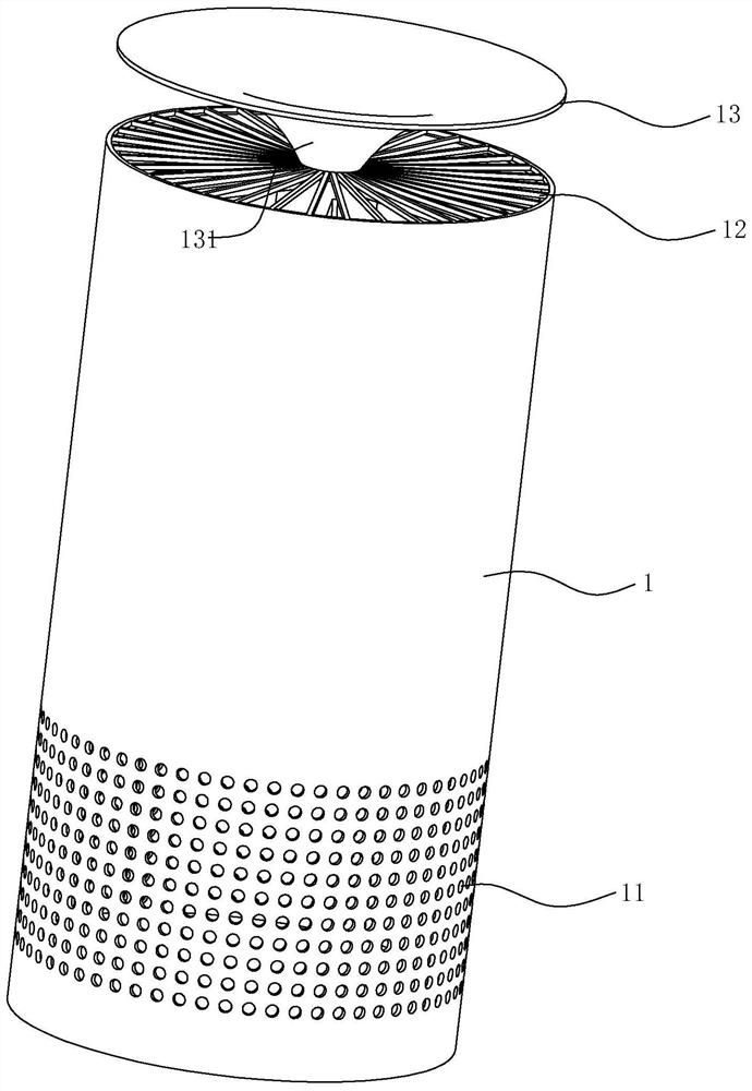
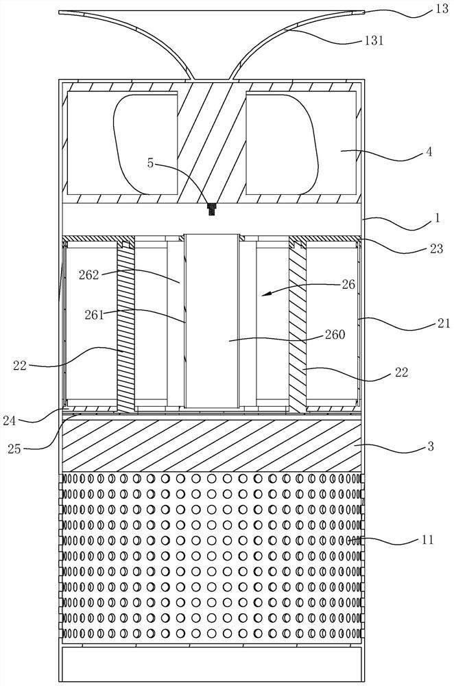
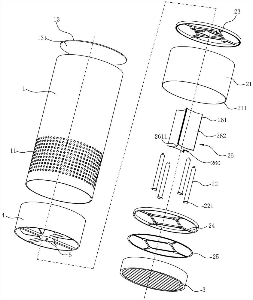
[0022] like Figures 1 to 4 As shown, the air sterilizer of this embodiment includes a casing 1 and a germicidal lamp assembly 2 arranged in the casing 1. The outer peripheral wall of the lower part of the casing 1 has several air inlets 11 and the top wall has air outlets 12. The germicidal lamp assembly 2 is located between the air inlet 11 and the air outlet 12 . The housing 1 of this embodiment is further provided with a filter assembly 3 for filtering particulate matter, and the filter assembly 3 is located upstream of the germicidal lamp assembly 2 . The casing 1 is provided with a fan assembly 4 for sucking indoor air into the casing 1 and discharging the sterilized air, the fan assembly 4 is arranged downstream of the germicidal lamp assembly 2, and the air inlet of the fan assembly 4 is arranged. Detection sensor 5 for detecting the concentration of microorganisms.
[0023] The germicidal lamp assembly 2 of the present embodiment includes a sleeve 21 and a germicidal lamp tube 22. The sleeve 21 is a metal tube that penetrates up and down, the metal tube is sleeved on the inner wall of the housing 1, and the germicidal lamp tube 22 is an ultraviolet lamp tube or pulse The light bulb, the germicidal bulb 22 is vertically arranged in the metal tube, and the inner wall of the metal tube forms a first reflective surface 211 corresponding to the germicidal bulb 22 .
[0024] In order to facilitate assembly, the germicidal lamp assembly 2 further includes an upper support frame 23 and a lower support frame 24. The upper support frame 23 is arranged on the top of the sleeve 21, the lower support frame 24 is arranged at the bottom of the sleeve 21, and the upper end of the germicidal lamp tube 22 is fixed on the On the upper support frame 23 , the lower end of the germicidal lamp tube 22 is fixed on the lower support frame 24 . In order to facilitate power supply to the germicidal lamp tube, the bottom of the lower support frame 24 hides a power connection piece 25 connected to the power supply, and the lower end of the germicidal lamp tube 22 has a power connection terminal 221 that is electrically connected to the power connection piece 25 through the lower support frame 24 .
[0025] The center part of the sleeve 21 in this embodiment is provided with a vertically extending reflective component 26 , an annular air guide channel 20 is formed between the reflective component 26 and the inner wall of the sleeve 21 , and the reflective component 26 has a first reflective component 26 , which is opposite to the sleeve 21 . The second reflective surface 262 corresponding to the surface 211 is provided. The germicidal lamp tube 22 is disposed in the air guide channel 20 and located between the first reflective surface 211 and the second reflective surface 262 . The first reflective surface 211 and the second reflective surface 262 can fully reflect the light emitted by the germicidal lamp 22, so that the light is more uniform everywhere, which is beneficial to improve the sterilization effect.
[0026] There are four germicidal lamps 22 in this embodiment and are uniformly distributed along the circumferential direction in the air guide channel 20 . Specifically, the reflector assembly 26 includes four reflector plates 261 so that each germicidal lamp tube 22 corresponds to a reflector plate respectively. 261 are connected end to end in the sleeve 21, two adjacent reflective plates 261 are tangent at the joint, each second reflective surface 262 is arranged toward the first reflective surface 211, and the germicidal lamp tube 22 is located at the center of the circle corresponding to the corresponding arc structure , and the circle where the arc structure is located is arranged tangentially to the first light emitting surface 211 . The circular area 200 where the above-mentioned arc-shaped structure is located is a range with relatively large light irradiation intensity, and due to the coordinated reflection of the first light-emitting surface 211 and the second light-reflecting surface 262, the light intensity distribution in the circular area 200 is uniform, which is conducive to improving the Bactericidal effect.
[0027] In this embodiment, the reflective plates 261 are transparent plates, and the reflective plates 261 are connected end to end to form an air circulation cavity 260 that penetrates up and down and is relatively closed in the circumferential direction. The inner wall of the reflective plates 261 is provided with a titanium dioxide coating 2611. With the above structure, the reflective plate 261 can cooperate with the first reflective surface 211 of the sleeve 21 to spread the light of the germicidal lamp 22 evenly, and at the same time, part of the light of the germicidal lamp 22 passes through the reflective plate 261 to excite the reflective plate The titanium dioxide coating 2611 on the inner wall of 261 makes it generate strong oxidizing substances (such as hydroxyl radicals, etc.) under light irradiation, which is used to decompose toxic and harmful gases such as formaldehyde in the air, purify the air efficiently, and can also effectively Kills a variety of bacteria and sterilizes the air.
[0028] In this embodiment, an upwardly extending air guide member 13 is arranged at the central part of the top wall of the housing 1. The outer diameter of the air guide member 13 gradually increases from bottom to top, and the outer peripheral wall is formed into an arc-shaped air guide surface that gradually arches upward. 131. The structure is beneficial to spread and disperse the sterilized air in the room quickly and evenly.
[0029]Using the sterilizer of this embodiment, the indoor air enters from the air inlet 11 and travels upwards. The particulate matter in the air is first filtered by the filter assembly 3, and then sterilized by the germicidal lamp assembly 2. The sterilized air passes through the detection sensor. 5. After detecting the concentration of microorganisms, it is discharged from the air outlet 12; when passing through the detection sensor 5, if the concentration of microorganisms is detected to be high, the light intensity of the germicidal lamp 22 can be enhanced. If the concentration of microorganisms is lower than the set detection concentration, Then, the light intensity of the germicidal lamp 22 can be reduced.

PUM

no PUM

Description & Claims & Application Information

We can also present the details of the Description, Claims and Application information to help users get a comprehensive understanding of the technical details of the patent, such as background art, summary of invention, brief description of drawings, description of embodiments, and other original content. On the other hand, users can also determine the specific scope of protection of the technology through the list of claims; as well as understand the changes in the life cycle of the technology with the presentation of the patent timeline. Login to view more.

Similar technology patents

Multifunctional warmer-dryer

PendingCN107366142APrevent agingImprove safety and qualityAir heatersTextiles and paperClothes hangerEngineering
Owner:中山蓝网物联技术有限公司

Prunus humilis fruit beverage

InactiveCN109170399AEliminate free radicals in the bodyPrevent agingFood thermal treatmentNatural extract food ingredientsFoods beveragesHawthorn fruit
Owner:北京沛时特医食品科技有限公司

Classification and recommendation of technical efficacy words

  • Improve lighting uniformity
  • Prevent aging

LED grille lamp

InactiveCN101865394AImprove lighting uniformityPoint-like light sourceElectric lightingMetal substrateOptoelectronics
Owner:KONKA GROUP

LED illumination device and illumination combination device thereof

PendingCN109681817AEnhance the light intensity of the wingsImprove lighting uniformityMechanical apparatusOutdoor lightingLight sourceIlluminance
Owner:史杰

Uniformity compensation device applied to large field-of-view montage illumination

ActiveCN102540736AGood lighting uniformityImprove lighting uniformityPhotomechanical exposure apparatusMicrolithography exposure apparatusLight sourceFeedback controller
Owner:SHANGHAI MICRO ELECTRONICS EQUIP (GRP) CO LTD

Special lens and glare-free blackboard lamp lighting system

PendingCN110242899AImprove lighting uniformityReduce macularLighting support devicesSemiconductor devices for light sourcesPhysicsLighting system
Owner:成都瀚德胜邦光学有限公司
Why Eureka
Try Eureka