
Appliance for cable stripping

A technology for cables and appliances, which is applied in the field of electric power maintenance tools, can solve problems such as easily damaged metal wires and complex cable stripping operations, and achieve the effects of labor-saving operation, avoiding damage to metal wires, and easy cutting length

Inactive Publication Date: 2020-11-13
GUANGDONG POWER GRID CO LTD +1
View PDF5 Cites 0 Cited by
  • Summary
  • Abstract
  • Description
  • Claims
  • Application Information

AI Technical Summary

Problems solved by technology

[0003] The object of the present invention is to provide a device for cable stripping, which can solve the problems of complicated and easy to damage metal wires in existing cable stripping operations

Method used


Image

  • Appliance for cable stripping

Examples


Embodiment 1

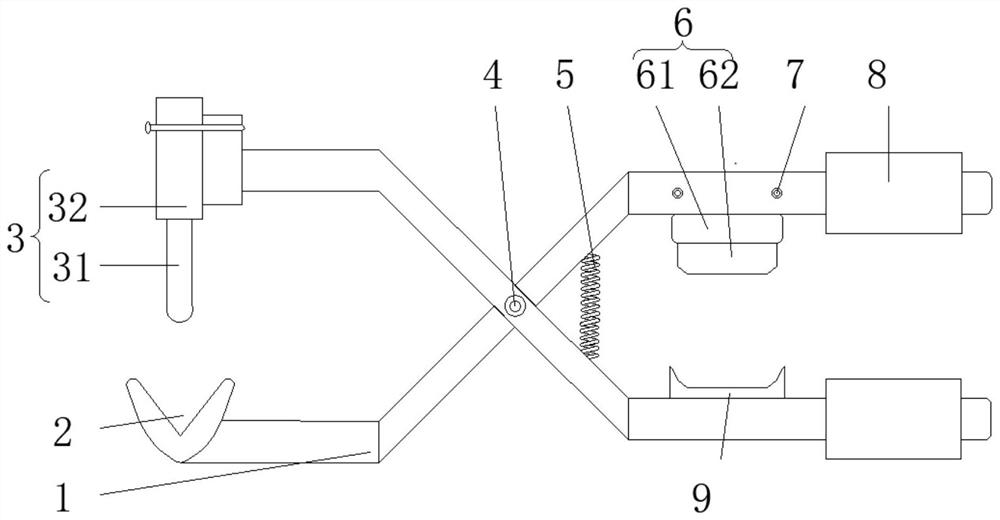
[0029] Such as figure 1 As shown, this embodiment provides an appliance for stripping cables, including a first support member 9 , a first cutting blade 6 , an elastic member 5 and two pliers 1 . The two pliers bodies 1 are hinged, and one end of the pliers body 1 forms a pliers head, and the other end forms a pliers handle. The inner side of one of the two pliers 1 is provided with a first support 9, and the other of the two pliers 1 is provided with a height-adjustable first cutting blade 6 corresponding to the position of the first support 9, And the first cutting blade 6 can cut the outer insulating layer of the cable along the radial direction of the cable. The elastic member 5 elastically connects the two pliers handles, and the elastic member 5 can drive the two pliers handles away from each other.

[0030] When cutting the cable, hold the two pliers handles tightly, the first cutting blade 6 and the first support member 9 will approach each other, make the first cutt...

Embodiment 2

[0052] This embodiment provides an appliance for stripping cables, which is further improved on the basis of Embodiment 1 to adjust the distance between the blade and the centerline of the support.

[0053] Specifically, the tool for stripping cables further includes spacers, which can be selectively arranged between the cutting blade and the pliers body 1 . Taking the second cutting blade 3 as an example, gaskets can be set between the second cutting blade 3 and the pliers body 1 according to specific needs, and the number of gaskets and the thickness of each gasket can be selected as required, thereby adjusting the second cutting blade 3. The relative position of the cutting blade 3 and the second supporting member 2, for example, can be such that the second cutting blade 3 can be located directly above the center line of the second bearing groove, or can be located on one side of the center line of the second bearing groove.


PUM


Abstract

The invention relates to the field of power maintenance tools, and particularly relates to an appliance for cable stripping. The appliance for cable stripping comprises two hinged clamp bodies, wherein one end of each clamp body forms a clamp head, and the other end forms a clamp handle. The appliance for cable stripping further comprises a first supporting piece, a first cutting blade and an elastic piece, wherein the first supporting piece is arranged on the inner side of one of the two clamp bodies, and a cable can be placed on the first supporting piece; the first cutting blade is arrangedon the other one of the two clamp bodies in a height-adjustable mode, corresponds to the first supporting piece in position and is used for cutting an insulating layer outside the cable in the radialdirection of the cable; and the elastic piece is elastically connected with the two clamp handles, and the elastic piece can drive the two clamp handles to deviate from each other. The appliance is suitable for cables with various wire diameters, an insulating layer can be cut off in the circumferential direction of the cable, the cutting length and depth are controlled, labor is saved during operation, the elastic piece can automatically reset after the appliance is used, and the clamp bodies do not need to be reset manually.

Description

technical field [0001] The invention relates to the field of electric maintenance tools, in particular to a device for peeling cables. Background technique [0002] At present, most of the existing cable appliances for power maintenance are tool pliers. When repairing cables, electric workers need to use the tool pliers to open the outer insulating layer of the cable, and then check and repair the inner wires of the cable. , the worker needs to clamp the cable through the pliers, then cut the outer insulation layer of the cable through the toothed structure inside the pliers, and finally use the pliers to clamp the outer insulation layer of the cable, and peel off the outer insulation layer from the outer side of the cable , the operation process is relatively complicated, time-consuming and labor-intensive, not only the length of the cable stripping cannot be determined, but also the inner metal wire of the cable is easily broken when the outer insulating layer is torn off ...

Claims


Application Information

Patent Timeline
Patent Type & Authority Applications(China)
IPC IPC(8): H02G1/12
CPCH02G1/1219
Inventor 周洋
Owner GUANGDONG POWER GRID CO LTD
Learn More