
Tolerance clamping mechanism for milling aluminum alloy profile

An aluminum alloy profile, milling technology, applied in metal processing machinery parts, metal processing equipment, clamping and other directions, can solve problems such as unfavorable production line layout, loose processing process, reduced processing accuracy, etc., to achieve compact layout, improve processing Accuracy, avoid loosening effect

Pending Publication Date: 2020-11-17
QINHUANGDAO FANGHUA SECM MACHINERY
View PDF0 Cites 0 Cited by
  • Summary
  • Abstract
  • Description
  • Claims
  • Application Information

AI Technical Summary

Problems solved by technology

The existing clamping mechanism mostly adopts the method of directly clamping the profile by the output force of the power source. This method has the following defects: it needs to be clamped by multiple power sources, which takes up a large space and is not conducive to the layout of the production line; There is a certain error, which can easily lead to inaccurate clamping in a certain direction, resulting in loosening during processing, thereby reducing processing accuracy

Method used


Image

  • Tolerance clamping mechanism for milling aluminum alloy profile
  • Tolerance clamping mechanism for milling aluminum alloy profile

Examples


Embodiment Construction

[0022] Below in conjunction with accompanying drawing and embodiment the present invention will be further described:

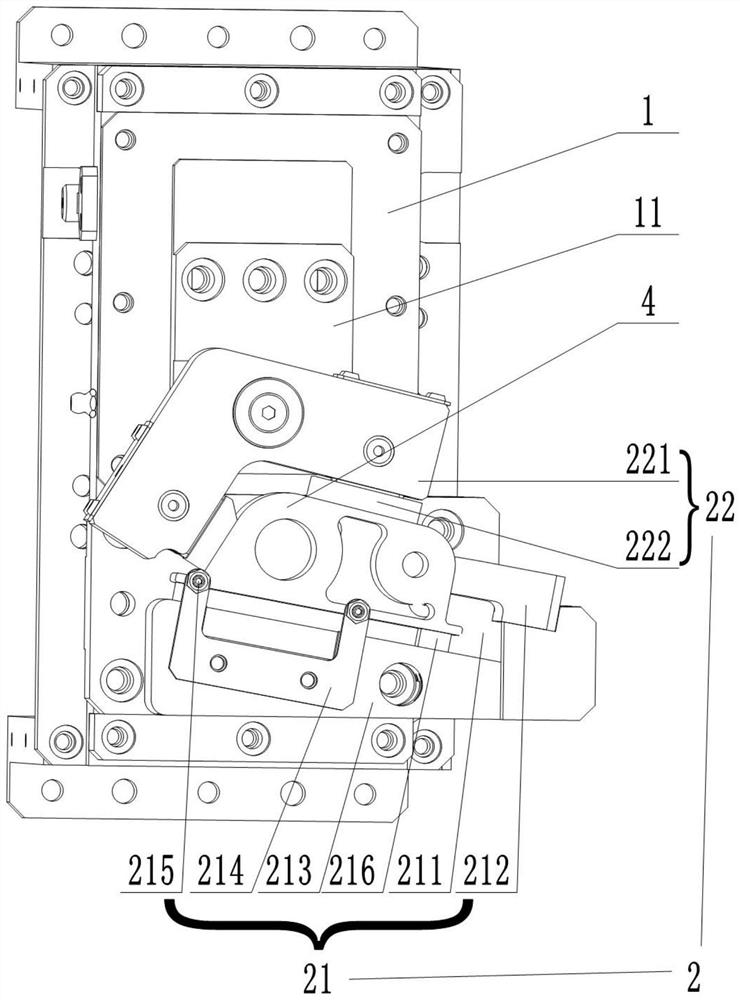
[0023] As shown in the figure, a tolerance clamping mechanism for milling aluminum alloy profiles includes:

[0024] Slide rail 1, the slide rail 1 is fixedly connected with the table top of the processing equipment, and the slide rail 1 is provided with a slider 11 for sliding;

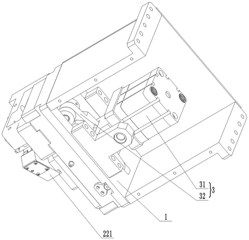
[0025] The clamping unit 2 is used to clamp the profile 4. The clamping unit 2 includes a fixed clamping part 21 and a movable clamping part 22. The fixed clamping part 21 and the movable clamping part 22 are located on the slide rail 1 and the slider 11 respectively. , the movable clamping part 22 is hinged with the slide rail 1 or the slider 11;

[0026] The clamping drive mechanism 3 is used to drive the clamping unit 2 to open and close. The clamping drive mechanism 3 includes a telescopic drive device 31, the fixed part of the telescopic drive device 31 is movably connected wi...


PUM


Abstract

The invention relates to a tolerance clamping mechanism for milling an aluminum alloy profile. The tolerance clamping mechanism comprises a sliding rail, a clamping unit and a clamping driving mechanism, wherein a sliding block is slidably arranged on the sliding rail; the clamping unit comprises a fixed clamping part and a movable clamping part, the fixed clamping part and the movable clamping part are located on the sliding rail and the sliding block correspondingly, and the movable clamping part is hinged to the sliding rail or the sliding block; and the clamping driving mechanism is used for driving the clamping unit to perform opening and closing actions, the clamping driving mechanism comprises a telescopic driving device, a fixed part of the telescopic driving device is movably connected with the sliding rail, and a movable part of the telescopic driving device is connected with the sliding rail and the sliding block through two connecting rods correspondingly. In this way, theprofile can be clamped tightly in all directions, the situation of loosening in the machining process is avoided, and machining precision is improved; through a connecting rod mechanism ingenious in structure, the fixed clamping part and the movable clamping part are matched, stable clamping of the profile can be achieved only through one power source, namely the telescopic driving device, the occupied space is small, and compact layout of a production line is facilitated.

Description

technical field [0001] The invention relates to the technical field of auto parts processing equipment, in particular to a tolerance clamping mechanism for aluminum alloy profile milling. Background technique [0002] When milling aluminum alloy profiles, it is necessary to fix the profiles to a certain position to ensure the accuracy of milling. The existing clamping mechanism mostly adopts the method of directly clamping the profile by the output force of the power source. This method has the following defects: it needs to be clamped by multiple power sources, which takes up a large space and is not conducive to the layout of the production line; There is a certain error, which can easily lead to inaccurate clamping in a certain direction, resulting in loosening during processing, thereby reducing processing accuracy. Contents of the invention [0003] The invention aims to solve the deficiencies of the prior art, and provides a tolerance clamping mechanism for aluminum...

Claims


Application Information

Patent Timeline
Patent Type & Authority Applications(China)
IPC IPC(8): B23Q3/00
CPCB23Q3/00
Inventor 不公告发明人
Owner QINHUANGDAO FANGHUA SECM MACHINERY
Learn More