
Textile industry dust collector

A technology for the textile industry and vacuum cleaners, applied in the directions of vacuum cleaners, suction nozzles, exhaust diffusers, etc., can solve the problems of slow absorption, flocs flying to damage parts, knotting, etc. Stabilize, increase the effect of the jitter effect

Active Publication Date: 2020-06-05
江苏奥纳麦格科技有限公司
View PDF6 Cites 1 Cited by
  • Summary
  • Abstract
  • Description
  • Claims
  • Application Information

AI Technical Summary

Problems solved by technology

[0004] The main purpose of the present invention is to overcome the deficiencies of the prior art and provide a vacuum cleaner for the textile industry to solve the problem that flocs will accumulate inside the equipment during mechanical processing, and the excessive pressure during air gun cleaning will cause flocs to fly and damage parts. Use a vacuum cleaner to vacuum parts in turn, the suction speed is slow, and the flocs are easily entangled by small parts and spinning threads during the suction process, which will pull the small parts and spinning threads, which will easily cause damage to small parts, and the spinning threads will be caught or broken. knotted problem

Method used


Image

  • Textile industry dust collector
  • Textile industry dust collector
  • Textile industry dust collector

Examples


Embodiment 1

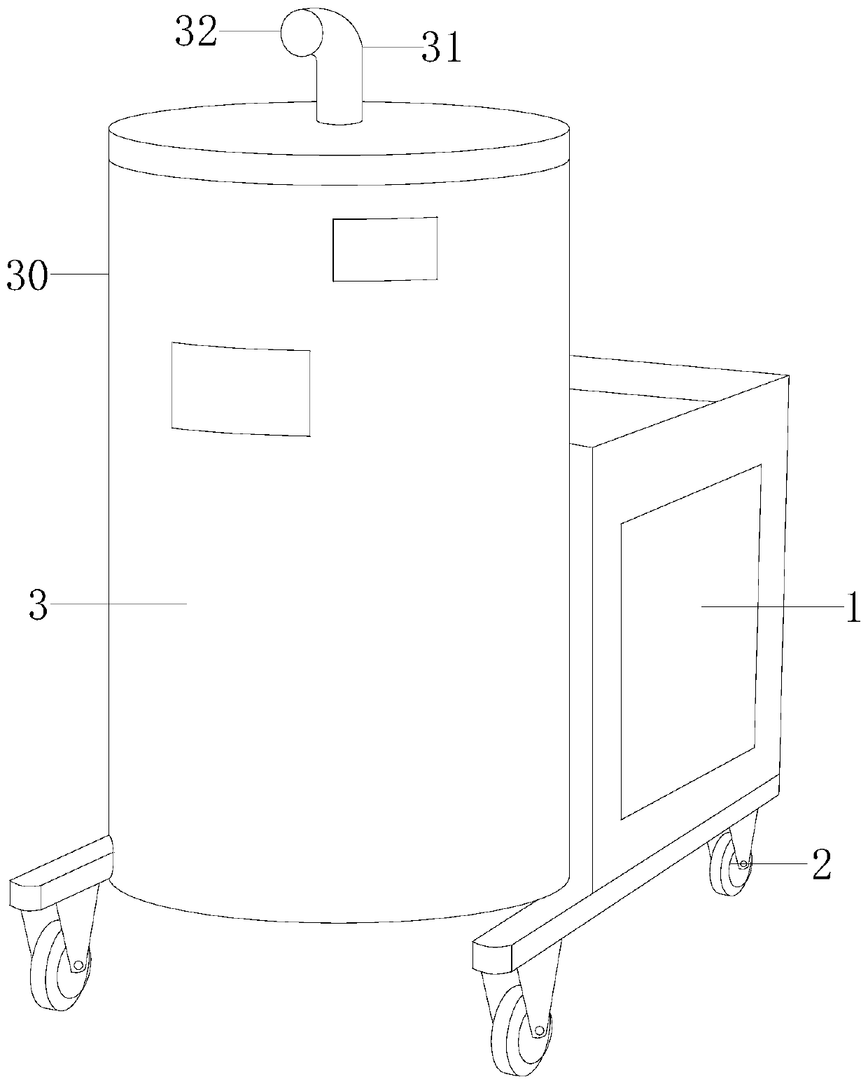
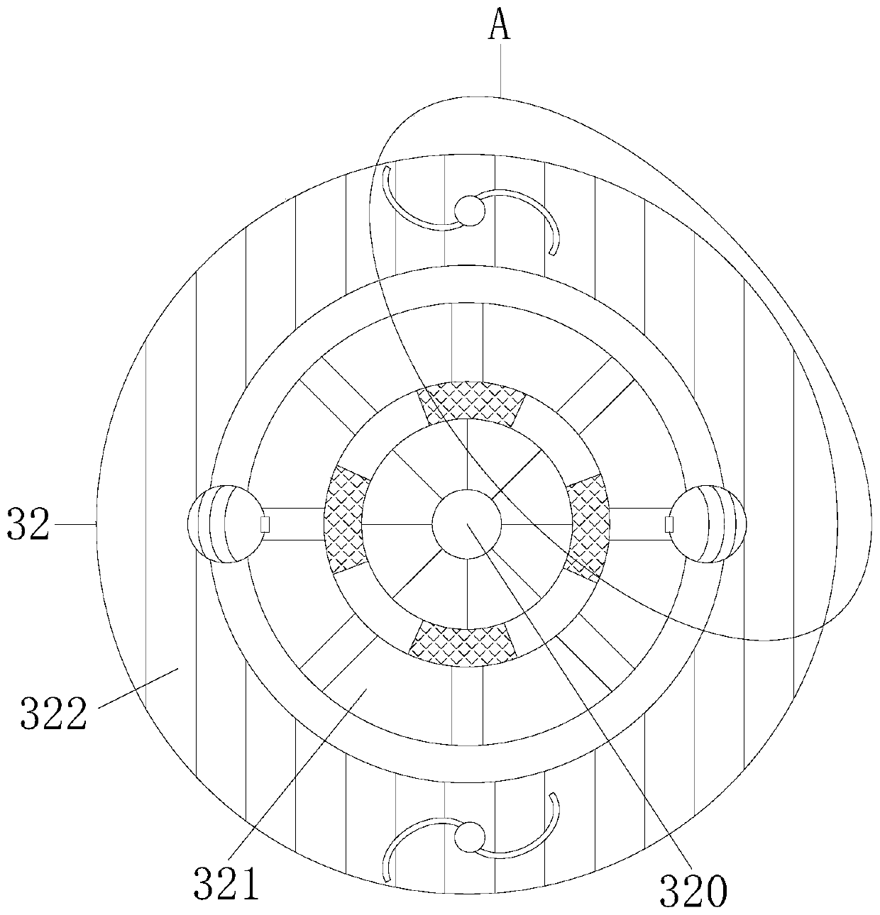
[0025] Example 1 see Figure 1-2 , the present invention provides a technical solution for a vacuum cleaner in the textile industry: its structure includes a chassis 1, a rack wheel 2, and a dust collection barrel 3, the chassis 1 and the rack wheel 2 are locked, and the chassis 1 and the dust collection barrel 3 are embedded, so The dust suction bucket 3 is arranged on the frame wheel 2, and the dust suction bucket 3 is composed of a cylinder body 30, a bobbin tube 31, and a nozzle structure 32. 32 is installed on the bobbin 31, and the flocs on the cleaning and collecting machine can be installed with the nozzle structure 32. After the nozzle structure 32 is removed, the diameter of the flocs collected will become larger, and the efficiency of the vacuum cleaner to collect the flocs on the ground will be improved. , the nozzle structure 32 includes a high-pressure air outlet structure 320, a middle ring stroke structure 321, and an outer ring soft wind structure 322. The so...

Embodiment 2

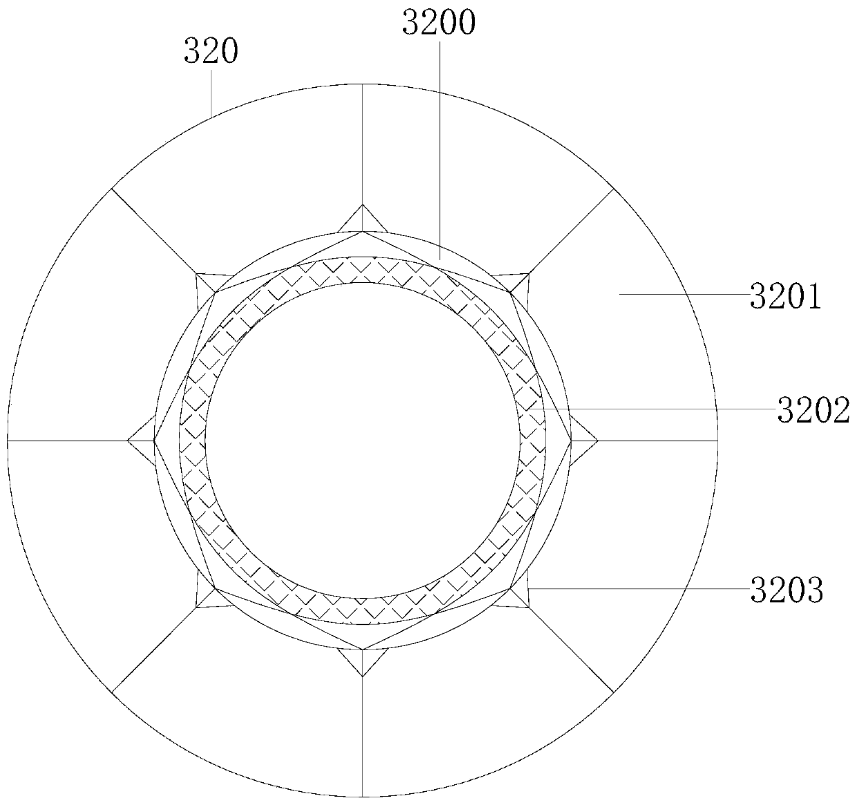
[0027] Example 2 see Figure 3-6, the present invention provides a technical solution for a vacuum cleaner in the textile industry: the structure of the high-pressure air outlet structure 320 includes a swivel 3200, a fixed plate 3201, a soft ring 3202, and a triangular clamp 3203, and the swivel 3200 is glued to the fixed plate 3201 , the triangular clamp 3203 is fixed on the swivel 3200 and the fixed plate 3201, the swivel 3200 is connected with the soft ring 3202, and the swivel 3200 is driven by variable diameter, which controls the spraying force and avoids scattered spraying , and also plays the role of fixing the soft ring 3202, the fixing plate 3201 is used to reinforce the high-pressure air outlet structure 320 as a whole, the triangular clamp 3203 is used to strengthen the installation position of the fixing plate 3201 and the swivel ring 3200, and the middle ring stroke structure 321 Including the air inlet main ring 3210, the fixing bar 3211, the air inlet auxiliar...


PUM


Abstract

The invention discloses a textile industry dust collector. The dust collector structurally comprises a case, frame wheels and a dust collection barrel, the case is locked with the frame wheels, the case and the dust collection barrel are embedded, the dust collection barrel is arranged on the frame wheels, and the dust collection barrel is composed of a barrel body, a barrel pipe and a pipe opening structure. The cylinder body is spirally connected with the barrel pipe; the pipe opening structure is arranged on the barrel pipe; and the pipe opening structure comprises a high-pressure air outlet structure, a middle-ring middle air structure and an outer-ring soft air structure. The high-pressure air outlet structure is connected with the middle-ring middle-air structural adhesive; the middle-ring middle air structure is connected with the outer-ring soft air structure; flocculated scraps are accumulated in the equipment; small-caliber air outlet of the high-pressure air outlet structuredoes not cause flying of flocks or damage to parts, the flocks are stably loosened through air blocking and air exhausting in the middle-ring air exhausting structure, and then the flocks are stablyloosened through soft air exhausting of the outer-ring soft air structure, so that the large-area cleaning efficiency is high, and the conditions that small parts are damaged and doubling threads arehooked off or knotted are avoided.

Description

technical field [0001] The invention relates to the field of vacuum cleaners for the textile industry, in particular to a vacuum cleaner for the textile industry. Background technique [0002] In the process of textile production and processing, it is inevitable to produce various dusts such as cotton wool, down, rags, and debris. These textile wastes are generally light in weight and fly around. They must be collected and cleaned by textile industrial vacuum cleaners. [0003] In the prior art, flocs will accumulate inside the equipment during mechanical processing. When the air gun is cleaned, the pressure will be too high, which will cause the flocs to fly and damage the parts. It is necessary to use a vacuum cleaner to vacuum the parts in turn. The suction speed is relatively slow, and the flocs are in the process of absorbing It is easy to be entangled by small parts and spinning threads, and the small parts and spinning threads are pulled, which is easy to cause damage...

Claims


Application Information

Patent Timeline
Patent Type & Authority Applications(China)
IPC IPC(8): A47L5/12A47L9/00A47L9/04
CPCA47L5/12A47L9/00A47L9/0081A47L9/0461
Inventor 景红锋
Owner 江苏奥纳麦格科技有限公司
Learn More