Angular momentum distribution method of redundant flywheel combination based on modified pseudo-inverse matrix

A technology of pseudo-inverse matrix and distribution method, which is applied in the directions of aerospace vehicles, aircraft, motor vehicles, etc., can solve the problems such as the decrease in the utilization rate of the angular momentum of a single flywheel and prolong the output time of a given torque, so as to achieve easy practical application, The effect of occupying less on-board resources and less computation

Active Publication Date: 2020-11-17
SHANGHAI AEROSPACE CONTROL TECH INST
View PDF4 Cites 4 Cited by
  • Summary
  • Abstract
  • Description
  • Claims
  • Application Information

AI Technical Summary

Problems solved by technology

[0005] The purpose of the present invention is to provide a method for distributing angular momentum of a redundant flywheel combination based on a modified pseudo-inverse matrix, which can effectively solve the problem that the angular momentum utilization rate of a single flywheel significantly decreases after the redundant flywheel combination introduces zero motion, and can Significantly extend the output time for a given torque

Method used


Image

  • Angular momentum distribution method of redundant flywheel combination based on modified pseudo-inverse matrix
  • Angular momentum distribution method of redundant flywheel combination based on modified pseudo-inverse matrix
  • Angular momentum distribution method of redundant flywheel combination based on modified pseudo-inverse matrix

Examples


Embodiment Construction

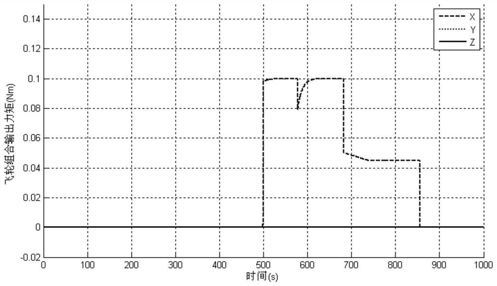
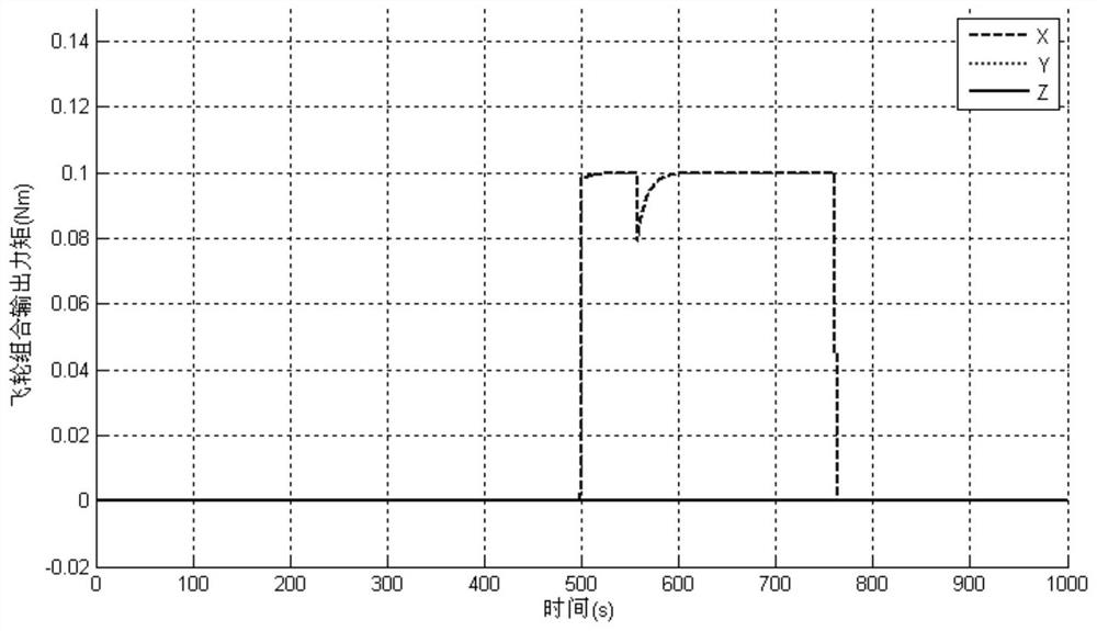
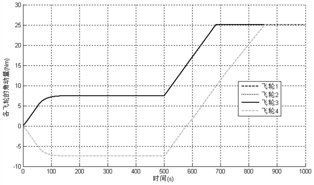
[0046] The following combination Figure 1 to Figure 5 , the technical content, structural features, achieved goals and effects of the present invention will be described in detail through preferred embodiments.

[0047] First of all, it is explained that in the present invention, the capital bold vector is uniformly used as the composite angular momentum or output / driving torque of the redundant flywheel combination, and the lower case bold vector is uniformly used as the angular momentum of each single flywheel in the redundant flywheel combination or output / drive torque.

[0048] Such as Figure 5 As shown, the angular momentum distribution method of the redundant flywheel combination based on the modified pseudo-inverse matrix provided by the present invention comprises the following steps:

[0049]S1. Calculate the reference drive torque of each flywheel in the redundant flywheel combination according to the flywheel angular momentum distribution algorithm based on the ...


PUM


Abstract

The invention relates to an angular momentum distribution method for a redundant flywheel combination based on a modified pseudo-inverse matrix, and the method comprises the steps: S1, calculating a reference driving moment of each flywheel in the redundant flywheel combination according to a three-axis instruction moment based on a flywheel angular momentum distribution algorithm combining the pseudo-inverse matrix with zero motion; S2, according to the reference driving torque of each flywheel, the current angular momentum of each flywheel and the upper limit of the angular momentum of eachflywheel, constructing a saturation variable, and evaluating the degree of each flywheel close to the saturation of the angular momentum; calculating a performance index correction coefficient by utilizing the saturated variable, and obtaining a corrected pseudo-inverse matrix by utilizing the saturated variable and the performance index correction coefficient; and S3, calculating the driving torque of each flywheel in the redundant flywheel combination according to the corrected pseudo-inverse matrix. According to the method, the problem that the angular momentum utilization rate of a singleflywheel is remarkably reduced after zero motion is introduced into a redundant flywheel combination can be effectively solved, and the output time of a given moment can be remarkably prolonged.

Description

technical field [0001] The invention relates to a method for distributing angular momentum of a redundant flywheel combination, in particular to a method for distributing angular momentum of a redundant flywheel combination based on a modified pseudo-inverse matrix. Background technique [0002] At present, the reaction flywheel based on the principle of angular momentum exchange to output torque is the most widely used attitude control actuator on three-axis attitude stabilization satellites. However, modern space missions put forward higher requirements on the life of the satellite. Therefore, in order to improve the reliability of the system, more than three flywheels are usually installed on the satellite to form a redundant flywheel combination as the actuator of the attitude control system. Since the number of flywheels is greater than the dimensionality of the output torque, the redundant flywheel combination can also bias the flywheel speed near the optimal operating...

Claims


Application Information

Patent Timeline
Patent Type & Authority Applications(China)
IPC IPC(8): B64G1/24B64G1/28
CPCB64G1/24B64G1/285B64G1/245
Inventor 刘刚张文政张家巍陈殿印张泽涛尹海宁叶立军
Owner SHANGHAI AEROSPACE CONTROL TECH INST
Why Eureka
Try Eureka