Crankshaft lubricating structure

A technology for lubricating structures and crankshafts, which is applied to crankshafts, liquid variable displacement machines, variable displacement pump components, etc. It can solve the problems of crankshaft climbing oil storage capacity, easy wear and lock of the frame, etc., to reduce wear and lock Die, improve lubricating performance, improve the effect of oil storage capacity

Pending Publication Date: 2020-11-17
ZHEJIANG MAIDI REFRIGERATION TECH CO LTD
View PDF0 Cites 2 Cited by
  • Summary
  • Abstract
  • Description
  • Claims
  • Application Information

AI Technical Summary

Problems solved by technology

[0003] The existing compressor crankshaft has a spiral groove structure outside the long axis of the crankshaft, which is driven by the rotor of the motor to rotate. Due to friction, there is relative movement between the refrigeration oil and the spiral groove of the crankshaft, so that the oil is pumped into the spiral groove path for lubrication. However, the oil storage capacity of the crankshaft with this structure is poor when climbing, and the rack is prone to wear and lock.

Method used


Image

  • Crankshaft lubricating structure
  • Crankshaft lubricating structure
  • Crankshaft lubricating structure

Examples


Embodiment

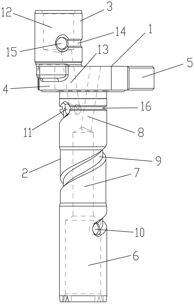
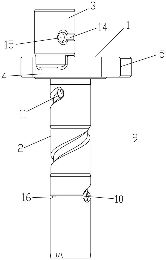
[0018] Embodiment: a kind of crankshaft lubricating structure, as Figure 1-Figure 6 As shown, it includes a crankshaft main body, the crankshaft main body includes a crankshaft major axis, an eccentric minor axis and an eccentric shaft, one side of the eccentric shaft is provided with a semicircular eccentric wheel, and the eccentric minor axis is arranged on a side away from the semicircular eccentric wheel The upper end of the eccentric shaft, the long axis of the crankshaft is arranged at the lower end of the center of the eccentric shaft, the inner side of the lower end of the long axis of the crankshaft is provided with a first channel, and the inner side of the middle end of the long axis of the crankshaft is provided with a second channel, The inner side of the upper end of the major axis of the crankshaft is provided with a third channel, the first channel communicates with the second channel, the second channel is the same as the third channel, and the lower side of t...

Embodiment approach

[0023] When the main body of the crankshaft rotates, due to the friction between the lubricating oil and the main body of the crankshaft, the lubricating oil moves upward through the first passage, and the lubricating oil flows through the first through hole to the spiral groove. When on the outer wall of the major axis, or when the ring oil groove is located outside the second through hole and on the outer wall of the major axis of the crankshaft, or when the ring oil groove is located outside the first through hole and on the outer wall of the major axis of the crankshaft and the outside of the second through hole and on the outer wall of the long axis of the crankshaft, the ring oil groove can improve the climbing oil storage capacity of the crankshaft, so that the lubricating oil can efficiently lubricate the crankshaft main body through the spiral groove, and improve the connection between the crankshaft main body and the engine. The lubricating performance between the rac...


PUM

PropertyMeasurementUnit
Widthaaaaaaaaaa

Abstract

The invention provides a crankshaft lubricating structure, and belongs to the technical field of compressor equipment. When annular oil grooves are located in the outer side of a first through hole and located in the outer wall of a crankshaft long shaft, or the annular oil grooves are located in the outer side of a second through hole and located in the outer wall of the crankshaft long shaft, orthe annular oil grooves are located in the outer side of the first through hole and located in the outer wall of the crankshaft long shaft, as well as located in the outer side of the second throughhole and located in the outer wall of the crankshaft long shaft, the annular oil grooves play a role in improving the climbing oil storage capacity of a crankshaft, lubricating oil can efficiently lubricate a crankshaft body through a spiral groove, the lubricating performance between the crankshaft body and a machine frame is improved, and abrasion and locking between the crankshaft body and themachine frame are reduced.

Description

technical field [0001] The invention belongs to the technical field of compressor equipment, and in particular relates to a crankshaft lubricating structure. Background technique [0002] With the rapid development of industrial technology, compressors have gradually become indispensable key equipment in various sectors of the country's economic pillar industries. The crankshaft is the main moving part of the reciprocating piston compressor, and its structural parameters have a decisive and important impact on the overall size, quality, working safety and life of the compressor. [0003] The existing compressor crankshaft has a spiral groove structure outside the long axis of the crankshaft, which is driven by the rotor of the motor to rotate. Due to friction, there is relative movement between the refrigeration oil and the spiral groove of the crankshaft, so that the oil is pumped into the spiral groove path for lubrication. However, the crankshaft with this structure has ...

Claims


Application Information

Patent Timeline
IPC IPC(8): F04B39/00F04B39/02F16C3/14
CPCF04B39/0094F04B39/0246F16C3/14
Inventor 邱建明周继辉
Owner ZHEJIANG MAIDI REFRIGERATION TECH CO LTD
Why Eureka
Try Eureka