Forced loosening type book supporting frame for reading

A support frame and book technology, applied in the field of support frames, can solve the problems of laborious adjustment of book placement height, inability to prevent muscle strain, and adjustment of book placement angle, so as to reduce physical exertion, easy adjustment, and convenient placement angle Effect

Inactive Publication Date: 2020-11-20
李云生
View PDF1 Cites 2 Cited by
  • Summary
  • Abstract
  • Description
  • Claims
  • Application Information

AI Technical Summary

Problems solved by technology

However, it only has the purpose of conveniently placing books for reading. From the perspective of intelligence, it cannot remind readers to change their posture to relax the cervical muscles after reading for a long time. It cannot prevent muscle strain caused by long-term reading, and cannot conveniently adjust books. It is impossible to adjust the inclination angle of the line of sight when reading to reduce physical exertion, and it is more laborious to adjust the height of books

Method used


Image

  • Forced loosening type book supporting frame for reading
  • Forced loosening type book supporting frame for reading
  • Forced loosening type book supporting frame for reading

Examples


Embodiment 2

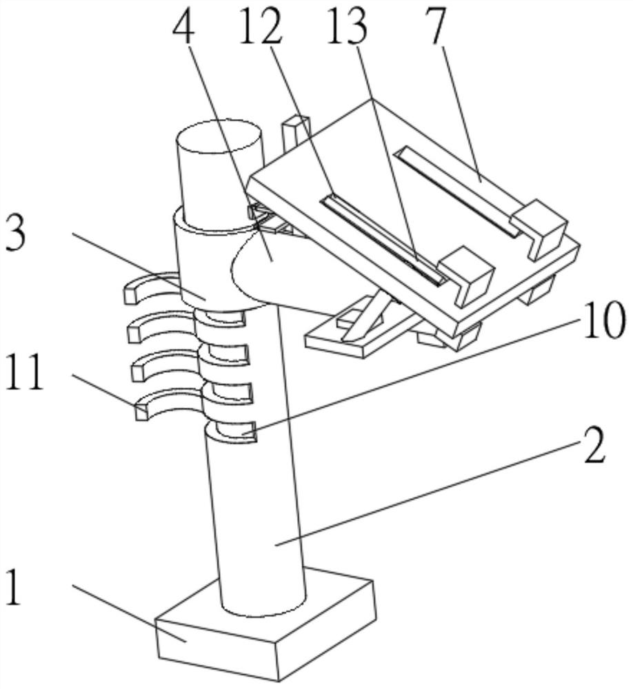
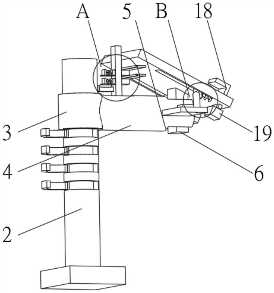
[0033] see Figure 1-4 , the present invention provides a technical solution: on the basis of Embodiment 1, the top of the placement plate 7 is symmetrically provided with inclined grooves 12, the inclined grooves 12 run through the placement plate 7, and there are sliding connections between the two sides of the inner wall of the inclined groove 12. Both sides of the plate 13 and the mounting rod 4 are fixedly connected with an extension plate 14 , and the top of the extension plate 14 is equipped with a forward pushing device 15 , which is connected to the push plate 13 in transmission.

[0034] The forward pushing device 15 includes an electronically controlled telescopic rod 151. A relay 152 is installed on one side of the electrically controlled telescopic rod 151. The relay 152 is electrically connected to the electrically controlled telescopic rod 151. The bottom of the electrically controlled telescopic rod 151 is connected to the extension plate 14. One end of the con...

Embodiment 3

[0038] see Figure 1-5 , the present invention provides a technical solution: on the basis of Embodiment 1, a buffer groove 20 is provided on the bottom of the lifting sleeve 3 away from the installation rod 4, and the top of the inner wall of the buffer groove 20 is fixedly connected with a buffer block through a buffer spring 21 twenty two.

[0039] The bottom of the buffer block 22 is provided with a rubber groove 23, the top of the inner wall of the rubber groove 23 is fixedly connected with a rubber block 24, the bottom of the rubber block 24 extends to the outside of the rubber groove 23, and both sides of the rubber block 24 are fixedly connected with a bump 25, An end of the protrusion 25 away from the rubber block 24 passes through the buffer block 22 and extends to the outside of the buffer block 22 .

[0040] During use, the lifting sleeve 3 is raised to the highest point along the support rod 2, and the support plate 11 is rotated until reaching the outside of the...


PUM


Abstract

The invention discloses a forced loosening type book supporting frame for reading and to the technical field of support frames. The frame comprises a base, and the top of the base is fixedly connectedwith a supporting rod. And the outer side of the supporting rod is sleeved with a lifting sleeve, one side of the lifting sleeve is fixedly connected with a mounting rod, a rotating groove is formedin the end, away from the lifting sleeve, of the mounting rod, a rotating block is rotatably connected between the two sides of the rotating groove, a containing plate is fixedly connected to the topof the rotating block, and a sliding groove is formed in the top of the mounting rod. According to the invention, the intelligent degree of the book supporting frame can be improved; a reader is reminded of changing postures to relax cervical vertebra muscles after long-time use and reading, the problem of muscle injury caused by long-time reading is prevented, the placement angle of a book can beconveniently adjusted, the reader can reach the optimal sight angle during reading, physical exhaustion of reading is reduced, and meanwhile the placement height of the book can be easily adjusted.

Description

technical field [0001] The invention relates to the technical field of support frames, in particular to a forced-relaxation book support frame for reading. Background technique [0002] At present, there are more and more people who like to read books, and the use of various support frames that help people to read is more and more widely used. People often use them when they are in the car, but holding books for a long time will cause pain in the arms, which is not conducive to long-term maintenance. human health. [0003] Chinese invention CN106579768A discloses a vehicle book support frame, which comprises an adjustment rod, a placement plate, a mounting plate, a suction cup, a support arm, an adjustment switch, a rotating shaft, a telescopic rod, a bearing pin, and a support plate. The support plate is a double-layer structure, the upper layer is a bookshelf board, the lower floor is an adjustment board, the bookshelf board and the adjustment board are connected by a bra...

Claims


Application Information

Patent Timeline
Patent Type & Authority Applications(China)
IPC IPC(8): A47B23/00A47B23/06F16F15/067
CPCA47B23/00A47B23/06F16F15/067
Inventor 李云生
Owner 李云生
Why Eureka
Try Eureka