
Eyeglass corner polishing equipment for manufacturing eyeglasses

A lens and edge technology, which is applied in the field of lens edge grinding equipment for glasses manufacturing, can solve the problems of cumbersome, labor-intensive, and low work efficiency, and achieve the effects of improving work efficiency, simple operation, and saving manpower

Active Publication Date: 2020-11-20
浙江维真医疗科技有限公司
View PDF7 Cites 8 Cited by
  • Summary
  • Abstract
  • Description
  • Claims
  • Application Information

AI Technical Summary

Problems solved by technology

[0006] In order to overcome the disadvantages of the current lens grinding operation process that is relatively cumbersome, the work efficiency is low, and the lens needs to be placed and taken out manually during the operation, which is relatively labor-intensive, the technical problem to be solved by the present invention is to provide a simple operation that can Lens edge grinding equipment for glasses manufacturing that improves work efficiency and saves manpower

Method used


Image

  • Eyeglass corner polishing equipment for manufacturing eyeglasses
  • Eyeglass corner polishing equipment for manufacturing eyeglasses
  • Eyeglass corner polishing equipment for manufacturing eyeglasses

Examples


Embodiment 1

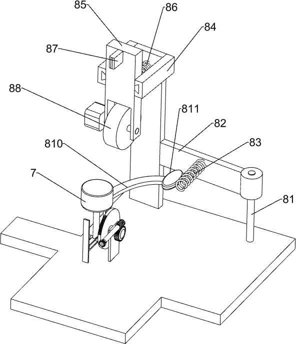
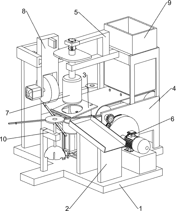
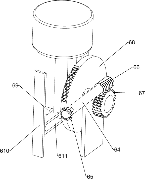
[0028] A lens edge grinding equipment for glasses manufacturing, such as Figure 1-5 As shown, it includes a bottom plate 1, a leakage rack 2, a placement plate 3, a frame 4 and a bracket 5, the front side of the top of the bottom plate 1 is connected with a leakage rack 2, and the rear side of the top of the leakage rack 2 is connected with a placement plate 3. The board 3 is set at an inclination, the top of the bottom plate 1 is connected with a frame 4 in the middle, the upper left side of the frame 4 is connected with a bracket 5, and also includes a transmission component 6, a clamping component 7 and a grinding component 8, and the bottom plate 1 is provided with a transmission component 6. A clamping component 7 is provided between the bracket 5 and the transmission component 6 , and the clamping component 7 is connected to the transmission component 6 , and a grinding component 8 is provided between the bottom plate 1 and the clamping component 7 .

[0029] The transm...

Embodiment 2

[0034] On the basis of Example 1, such as Figure 6 As shown, a feed assembly 9 is also included, and the feed assembly 9 includes a barrel 91, a roller 92, a connecting gear 93, a conveyor belt 94, a dial 95 and a second arc rack 96, and the upper part of the right side of the frame 4 is connected with the barrel 91, the left and right sides of the frame 4 are rotatably connected with a drum 92, the drive shaft of the left drum 92 is connected with a connecting gear 93, a conveyor belt 94 is wound between the drums 92 on both sides, and the discharge end of the barrel 91 is located at On the top of the conveyor belt 94 , multiple groups of shifting blocks 95 are evenly spaced connected to the conveyor belt 94 , and a second arc-shaped rack 96 is connected to the first turntable 62 , and the second arc-shaped rack 96 will mesh with the connecting gear 93 .

[0035] When placing the lenses, the lenses can be stacked in the barrel 91, and the bottom lens will contact the conveyo...


PUM


Abstract

The invention relates to polishing equipment, in particular to eyeglass corner polishing equipment for manufacturing eyeglasses. The eyeglass corner polishing equipment for manufacturing the eyeglasses is simple in operation, and capable of improving working efficiency and saving manpower. The eyeglass corner polishing equipment comprises a bottom plate, a storage plate, a frame, a bracket and a transmission assembly, wherein one side of the top of the bottom plate is connected with a leaking frame; the storage plate is connected to one side of the top of the leaking frame and is obliquely arranged; the frame is connected in the middle of the top of the bottom plate; the bracket is connected to the upper part of one side of the frame; and the transmission assembly is arranged on the bottomplate. According to the eyeglass corner polishing equipment, the eyeglasses are polished through the matched operation of the transmission assembly, a clamping assembly and a polishing assembly, so that the effect of polishing the eyeglasses is achieved.

Description

technical field [0001] The invention relates to a grinding device, in particular to a lens edge grinding device for glasses manufacturing. Background technique [0002] Lenses are transparent materials with one or more curved surfaces made of optical materials such as glass or resin. After polishing, they are often assembled with spectacle frames to form glasses, which are used to correct the user's vision and obtain a clear vision. There are many ways to classify lenses, which can be classified according to the material, function and surface treatment process of the lens. When the lens is put into the spectacle frame, it needs to be polished, and the lens is polished to a specific shape, and then put into the spectacle frame. [0003] At present, the way to polish the lens is usually to manually place the lens on the grinding equipment for grinding, and then take out the spectacle lens after grinding. Frequent placement and removal of lenses is labor-intensive. [0004] ...

Claims


Application Information

Patent Timeline
Patent Type & Authority Applications(China)
IPC IPC(8): B24B9/14B24B41/00B24B41/02B24B41/06B24B27/00
CPCB24B9/14B24B41/005B24B41/02B24B9/146B24B27/00
Inventor 廖良玉
Owner 浙江维真医疗科技有限公司
Learn More