
Valve wheel rotary device

A technology of rotating devices and door wheels, which is applied in the manufacture of tools, hand-held tools, etc., and can solve problems such as time-consuming and labor-intensive

Inactive Publication Date: 2020-11-20
SHENHUA SHENDONG POWER
View PDF5 Cites 0 Cited by
  • Summary
  • Abstract
  • Description
  • Claims
  • Application Information

AI Technical Summary

Problems solved by technology

[0004] The purpose of the embodiment of the present application is to provide a valve wheel rotating device, which can solve the time-consuming and labor-intensive problem of the current valve opening and closing control methods

Method used


Image

  • Valve wheel rotary device
  • Valve wheel rotary device
  • Valve wheel rotary device

Examples


Embodiment Construction

[0020] The following will clearly and completely describe the technical solutions in the embodiments of the present application with reference to the drawings in the embodiments of the present application. Obviously, the described embodiments are part of the embodiments of the present application, not all of them. Based on the embodiments in this application, all other embodiments obtained by persons of ordinary skill in the art without creative efforts fall within the protection scope of this application.

[0021] The terms "first", "second" and the like in the specification and claims of the present application are used to distinguish similar objects, and are not used to describe a specific sequence or sequence. It should be understood that the terms so used are interchangeable under appropriate circumstances such that the embodiments of the application can be practiced in sequences other than those illustrated or described herein, and that references to "first," "second," et...


PUM


Abstract

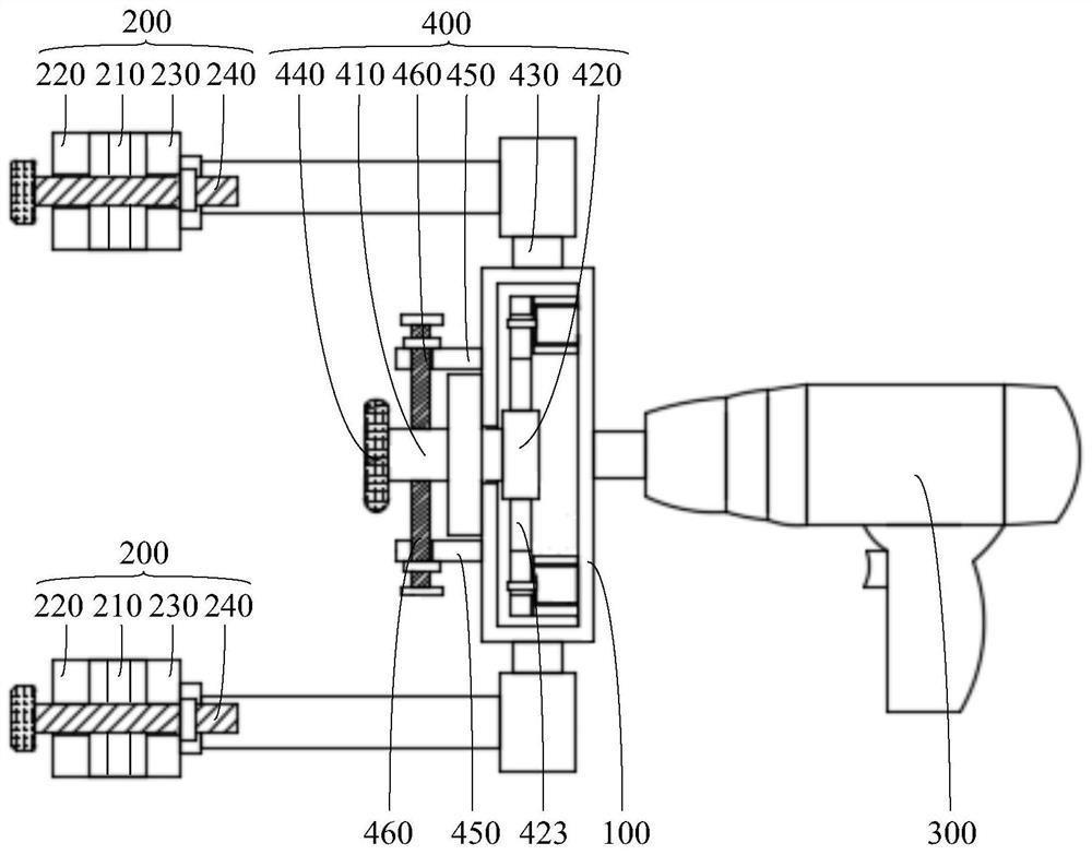
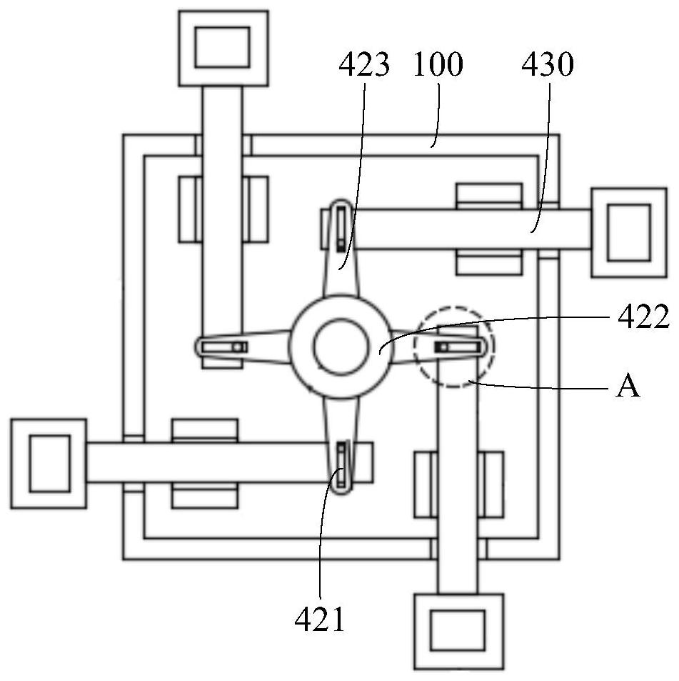
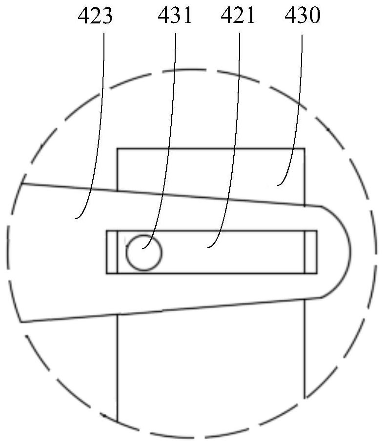
The invention discloses a valve wheel rotary device and belongs to the technical field of valve control. The valve wheel rotary device comprises a rotary bracket (100), at least two clamping mechanisms (200) and an electric driving mechanism (300); one end of each of the clamping mechanisms (200) is connected with the rotary bracket (100); all clamping mechanisms (200) are distributed at intervalsin the circumferential direction of the rotary bracket (100) and can be fixed with a valve wheel; the electric driving mechanism (300) is connected with the rotary bracket (100) and drives the clamping mechanisms (200) to rotate through the rotary bracket (100). According to the scheme, the problem that the current valve on-off control manner wastes time and labor is solved.

Description

technical field [0001] The application belongs to the technical field of valve control, and in particular relates to a valve wheel rotating device. Background technique [0002] Valves are used for fluid control in industrial control systems, and have the functions of diversion, cut-off, throttling, check, diversion or overflow and pressure relief. [0003] The existing valve opening and closing control is generally realized by manually turning the valve door wheel, or relying on external equipment to open and close manually. This method is very labor-intensive, especially when the number of valves increases, not only the operation is cumbersome The time cost will lead to an invisible increase in labor costs. When an emergency occurs, if the valve cannot be opened and closed in time, the accident will be further expanded. Therefore, the valve opening and closing control method under this scheme is time-consuming and laborious. Contents of the invention [0004] The purp...

Claims


Application Information

Patent Timeline
Patent Type & Authority Applications(China)
IPC IPC(8): B25B33/00
CPCB25B33/00
Inventor 张晓龙
Owner SHENHUA SHENDONG POWER
Learn More