
Safety belt force reducing device

A seat belt and power wheel technology, applied in the field of seat belt force reduction device, can solve the problems of poor comfort, achieve the effect of convenient operation and improve the comfort of use

Inactive Publication Date: 2020-11-20
ZHEJIANG LEAPMOTOR TECH CO LTD
View PDF8 Cites 0 Cited by
  • Summary
  • Abstract
  • Description
  • Claims
  • Application Information

AI Technical Summary

Problems solved by technology

[0004] The purpose of the present invention is to overcome the problems of poor comfort when the seat belt is pulled out in the above-mentioned background technology, and when the webbing is recovered, the lock tongue will hit the interior guard and damage the guard due to the rapid recovery of the webbing, and provides a seat belt reducing Power device, easy to operate, effectively improves the operating comfort of the driver when wearing the seat belt, and avoids the fast retraction and swing of the webbing after the seat belt is unlocked and damages the interior guard plate

Method used


Image

  • Safety belt force reducing device
  • Safety belt force reducing device
  • Safety belt force reducing device

Examples


Embodiment 1

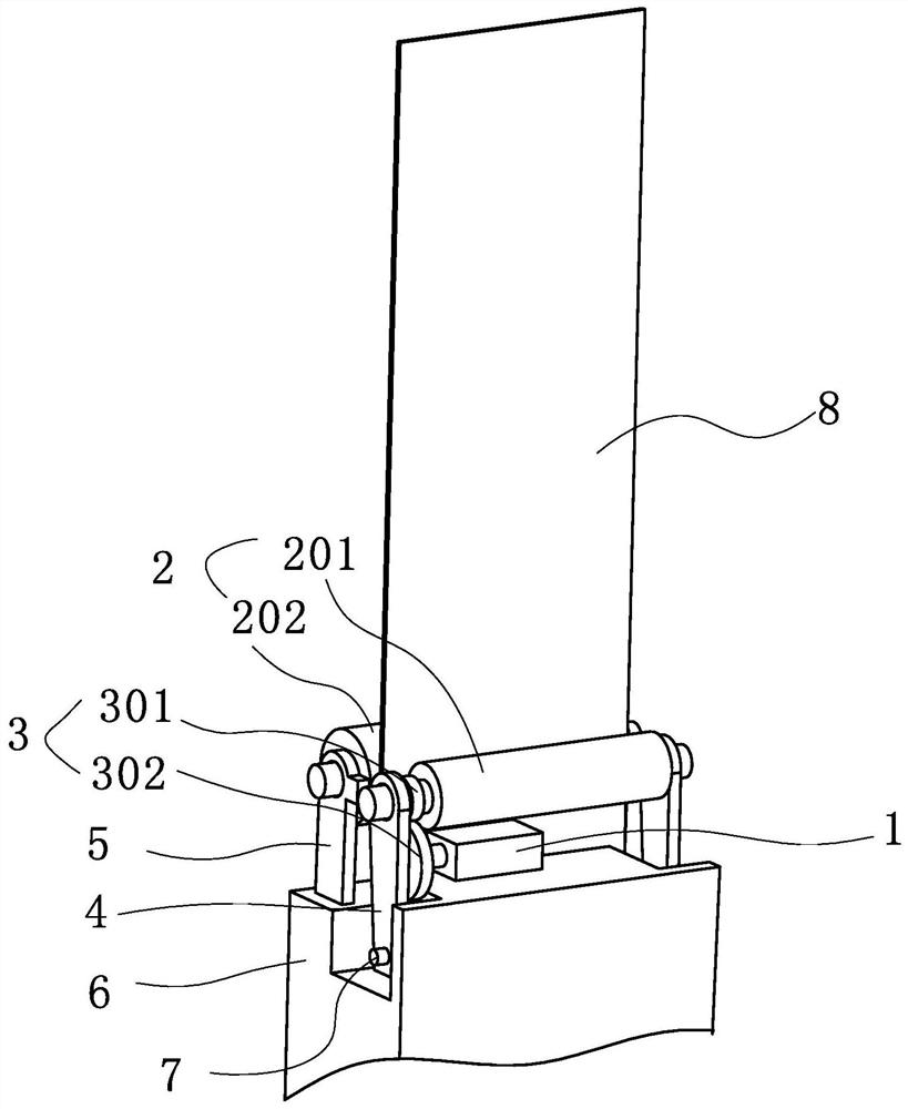
[0035] Such as figure 1 In the shown embodiment 1, a safety belt force reducing device includes a force reducing mechanism 10 and a fixing seat 6, the force reducing mechanism 10 is installed on the fixing seat 6, and the fixing seat 6 is arranged at the outlet of the retractor 11, namely The force reduction mechanism 10 is arranged at the exit of the retractor 11, which is convenient for controlling the webbing 8 when the ribbon 8 is pulled out; the force reduction mechanism 10 includes a force reduction wheel assembly 2, a motor 1 and a control assembly, wherein the force reduction wheel assembly 2 includes The driving wheel 201 and the driven wheel 202, the driving wheel 201 and the driven wheel 202 are respectively arranged on both sides of the webbing, the auxiliary webbing 8 is pulled out and recovered, the driving wheel 201 is connected to the motor 1, and the control assembly includes a motor for detecting the motion state of the webbing 8 A sensor and a controller for...

Embodiment 2

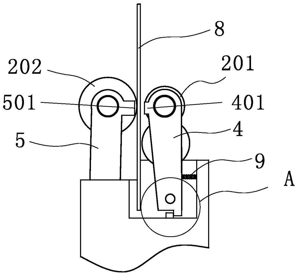
[0040] Such as figure 2 , Figure 5 As shown, the technical solution of embodiment 2 is basically the same as the technical solution of embodiment 1, the difference is that it also includes a support plate 5 and a fixed plate, and the two ends of the driven wheel 202 are respectively fixed on the two support plates 5 to drive Both ends of the wheel 201 are respectively fixed on two rotating plates 4, and the supporting plate 5 and the rotating plate 4 are respectively used to fix the driving wheel 201 and the driven wheel 202, so as to control the distance between the driving wheel 201 and the driven wheel 202.

[0041] Further, a stop tooth 501 is provided on the support plate 5, a limit tooth 401 corresponding to the stop tooth 501 is provided on the rotating plate 4, the stop tooth 501 is set as an electromagnet, and the lower side of the rotating plate 4 is connected to the A rotating structure is arranged between the fixed bases 6, and the rotating structure includes a ...

Embodiment 3

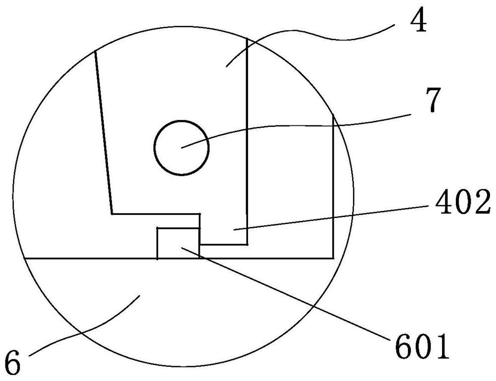
[0044] Such as image 3 As shown, the technical solution of embodiment 3 is basically the same as the technical solution of embodiment 2, the difference is that: the lower end of the rotating plate 4 is provided with a limiting structure for controlling the rotation angle of the rotating plate 4, and the limiting structure includes a The limit protrusion 402 at the lower end of the rotating wheel corresponds to the limit block 601 arranged on the fixed seat 6. The limit protrusion 402 and the limit block 601 control the rotation range of the rotating plate 4, avoiding the rotation of the rotating plate 4 during the reset process. Larger swings in the middle cause inconvenience.


PUM


Abstract

The invention discloses a safety belt force reducing device. The device comprises a force reducing mechanism and a fixed seat arranged at an outlet of a retractor, wherein the force reducing mechanismis installed on the fixed base and includes a force reducing wheel assembly used for assisting in pulling out or drawing back a woven belt, a motor used for driving the force reducing wheel assemblyto move and a control assembly used for rotating the motor; and the control assembly is electrically connected with the motor, and the motor is in transmission connection with the force reducing wheelassembly. The invention provides the safety belt force reducing device which is convenient to operate, effectively improves the operation comfort when a driver fastens a safety belt, and prevents a woven belt from rapidly retracting and swinging to knock an interior trim protection plate after the safety belt is unlocked.

Description

technical field [0001] The invention relates to the field of auto parts, in particular to a safety belt force reducing device. Background technique [0002] Seat belts are the key parts to protect the safety of drivers and passengers on the seats. The related parts mainly include lock tongue, webbing and retractor. When in use, they are mainly fixed on the seat belt buckle by the lock tongue. The seat belt is fixed, and the webbing of the seat belt is mainly recovered through the coil spring inside the retractor after the seat belt is unlocked. When the driver and passengers use the seat belt to pull the webbing out of the retractor, the greater the preload of the coil spring, the greater the pre-tightening force, causing the driver and passengers to pull out the webbing more and more forcefully, making the operation uncomfortable; After the driver and passenger unlock the seat belt, because the coil spring is in a position with a large preload at this time, the recovery fo...

Claims


Application Information

Patent Timeline
Patent Type & Authority Applications(China)
IPC IPC(8): B60R22/34
CPCB60R22/34
Inventor 李海锋
Owner ZHEJIANG LEAPMOTOR TECH CO LTD
Learn More