
Lifting belt conveying mechanism with separable transmission

A technology of conveying mechanism and lifting belt, applied in conveyor, transportation and packaging, etc., can solve the problems of complex production process, large dust hazard and explosion risk, low degree of automation, etc. The length of the production line and the effect of facilitating post-maintenance

Pending Publication Date: 2020-11-20
百特(福建)智能装备科技有限公司
View PDF0 Cites 0 Cited by
  • Summary
  • Abstract
  • Description
  • Claims
  • Application Information

AI Technical Summary

Problems solved by technology

[0002] The production process of fireworks is complex and varied, among which the fireworks barrels in the charging process are filled with flammable and explosive fireworks ingredients such as carbon powder, high potassium, sulfur, silver powder and rock powder. These fireworks drugs have relatively large dust hazards and explosion hazards. risk
The heavy work in the production process of fireworks is mostly carried out manually. The mechanical transmission of the conveyor belt often causes problems such as dust accumulation and jamming. There is a certain risk of explosion, and the linkage between various processes is complicated, resulting in a long production line. Inefficiency affects productivity
At present, there is still a large gap in the charging equipment for the inner barrel of fireworks. Although there are some related research and development equipment in the market, the technology is not yet mature and the degree of automation is low.

Method used


Image

  • Lifting belt conveying mechanism with separable transmission
  • Lifting belt conveying mechanism with separable transmission
  • Lifting belt conveying mechanism with separable transmission

Examples


Embodiment Construction

[0022] In order to make the purpose, technical solutions and advantages of the present invention clearer, the present invention will be further described in detail below in conjunction with the accompanying drawings. Obviously, the described embodiments are only some of the embodiments of the present invention, rather than all of them. Based on the embodiments of the present invention, all other embodiments obtained by persons of ordinary skill in the art without making creative efforts belong to the protection scope of the present invention.

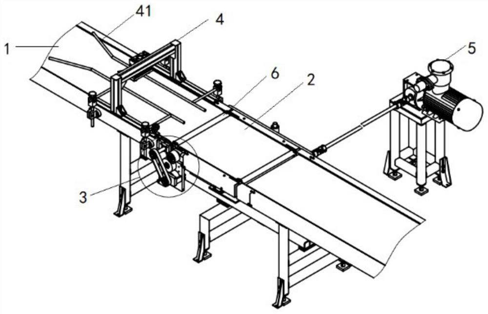
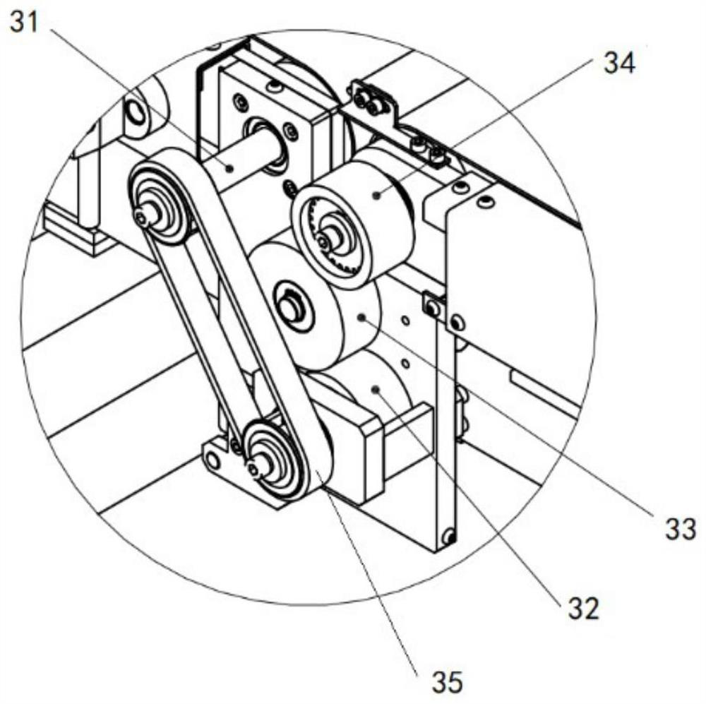
[0023] The following will be combined with figure 1 and figure 2 The present invention is described in detail. A lifting belt conveying mechanism with detachable transmission of the present invention includes a long conveyor belt 1, a liftable conveyor belt 2 and a friction wheel transmission device 3, and the liftable conveyor belt 2 is placed on the long conveyor belt 1. Upstream or downstream, the friction wheel transmission device...


PUM


Abstract

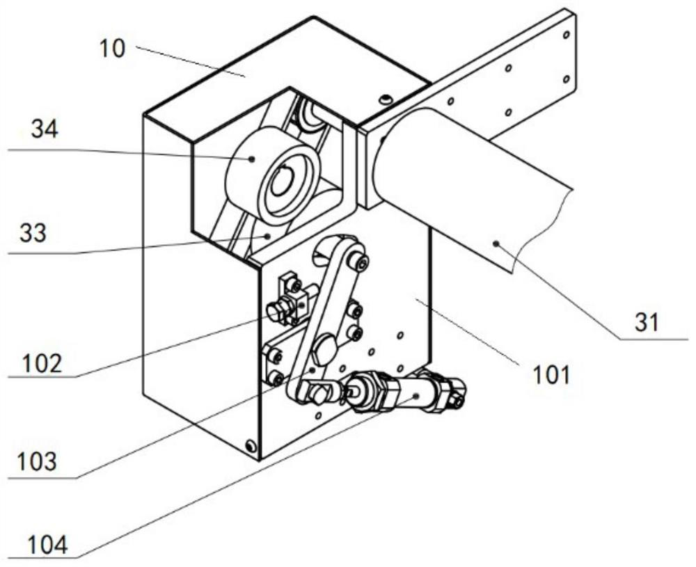
The invention provides a lifting belt conveying mechanism with separable transmission. The lifting belt conveying mechanism comprises a long conveying belt, a liftable conveying belt and a friction wheel transmission device, wherein the liftable conveying belt is arranged on the upstream or the downstream of the long conveying belt, and the friction wheel transmission device is arranged below theliftable conveying belt and used for controlling starting and stopping of the liftable conveying belt; and the friction wheel transmission device comprises a driving wheel, a friction wheel, a drivenwheel and a friction wheel separation mechanism, the driving wheel is transmitted to the driven wheel through the friction wheel, the driven wheel drives the liftable conveying belt to move, and the friction wheel separation mechanism controls contact or separation of the friction wheel and the driven wheel so as to control starting and stopping of the liftable conveying belt. The lifting belt conveying mechanism with the separable transmission is mainly used in an automatic firework inner tube charging production line, efficient workpiece conveying can be achieved, the length of the production line is shortened, the production cycle of a single piece is shortened, the production efficiency is improved, and contact between firework powder and a human body is reduced, so that harm of powderdust to human bodies is reduced.

Description

technical field [0001] The invention belongs to the technical field of firecracker inner cylinder charge equipment, and in particular relates to a lifting belt conveying mechanism with detachable transmission. Background technique [0002] The production process of fireworks is complex and varied, among which the fireworks barrels in the charging process are filled with flammable and explosive fireworks ingredients such as carbon powder, high potassium, sulfur, silver powder and rock powder. These fireworks drugs have relatively large dust hazards and explosion hazards. risk. The heavy work in the production process of fireworks is mostly carried out manually. The mechanical transmission of the conveyor belt often causes problems such as dust accumulation and jamming. There is a certain risk of explosion, and the linkage between various processes is complicated, resulting in a long production line. Inefficiency affects productivity. At present, there is still a large gap i...

Claims


Application Information

Patent Timeline
IPC IPC(8): B65G15/30
CPCB65G15/30
Inventor 陈财强曾庆生邓长斌
Owner 百特(福建)智能装备科技有限公司
Learn More