Optical system subassembly for automobile lighting

A technology for optical systems and automotive lighting, applied in the field of optical system sub-assemblies, can solve problems such as cumbersome assembly, and achieve an effect that is conducive to rapid assembly

Pending Publication Date: 2020-11-20
CHANGZHOU XINGYU AUTOMOTIVE LIGHTING SYST
View PDF0 Cites 0 Cited by
  • Summary
  • Abstract
  • Description
  • Claims
  • Application Information

AI Technical Summary

Problems solved by technology

[0003] In order to solve the problem of cumbersome assembly, the present invention provides an optical system sub-assembly for automotive lighting, including a shutter and a baffle horizontally arranged above the shutter, and the baffle is connected with the shutter through a snap-fit ​​structure. The baffle is connected, the clamping structure includes a number of slots and plugs arranged on the baffle, a stamping bridge is provided on the shutter, and the stamping bridge cooperates with the plug to limit the position. The shutter is provided with a number of transoms, and the transoms are snapped together with the slots

Method used


Image

  • Optical system subassembly for automobile lighting
  • Optical system subassembly for automobile lighting
  • Optical system subassembly for automobile lighting

Examples


Embodiment Construction

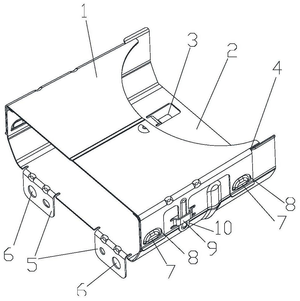
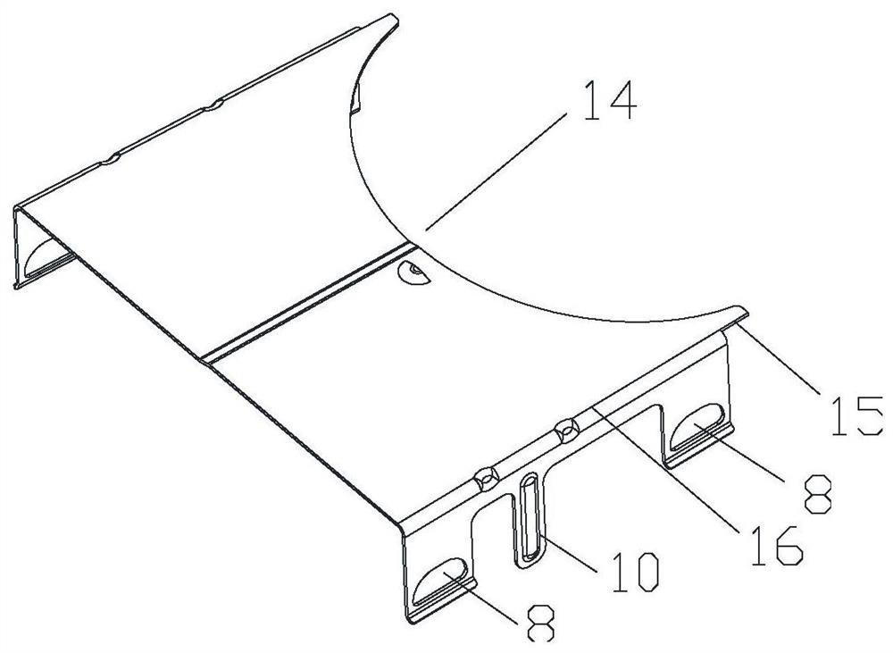
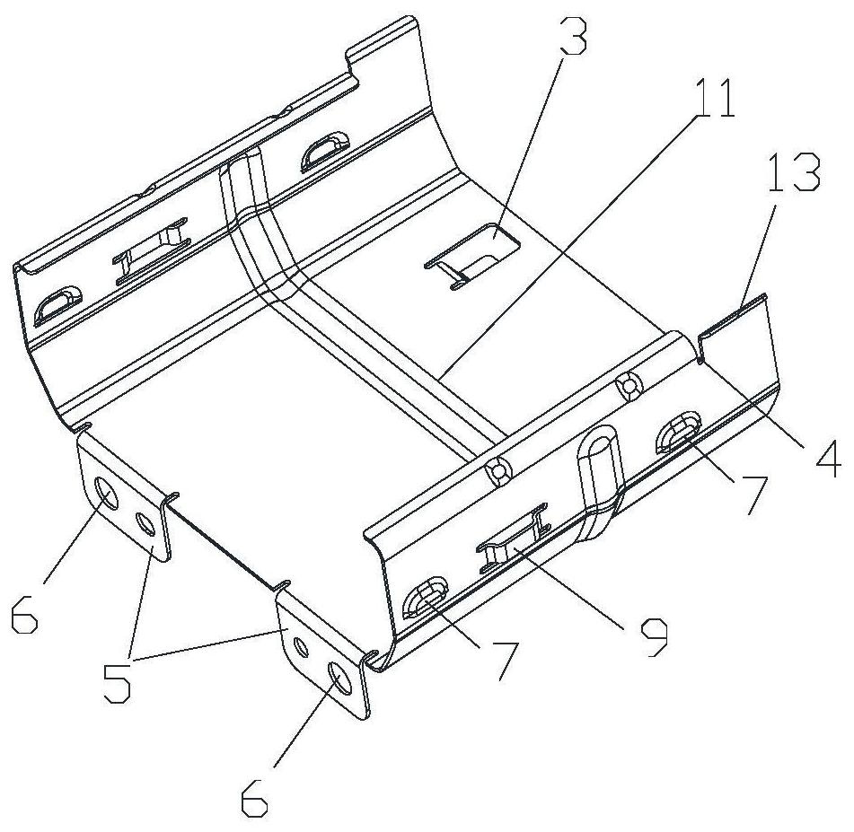
[0017] Such as figure 1 As shown, an optical system sub-assembly for automotive lighting includes a shutter 2 and a baffle 1 horizontally arranged above the shutter 2, and the baffle 1 is connected to the baffle 1 through a snap-fit ​​structure. connect. Such as figure 2 and 3 As shown, the clamping structure includes several slots 8 and plugs 10 arranged on the baffle 1, and the shutter 2 is provided with a stamping bridge 9, and the stamping bridge 9 cooperates with the plug 10 to perform Position limit, the shutter 2 is provided with a number of transoms 7, and the transoms 7 are snapped together with the card slots 8. The baffle plate 1 is clamped with the shutter 2, which is convenient for disassembly and assembly.

[0018] Such as image 3 As shown, the two sides of the shutter 2 are bent and extended inwardly to form a mounting surface 12, and the remaining part forms a limiting surface 13. The limiting surface 13 is located at one end of the mounting surface 12, ...


PUM


Abstract

The invention relates to an optical system subassembly for automobile lighting. The optical system subassembly comprises a light shielding device and a baffle horizontally arranged above the light shielding device. The baffle is connected with the light shielding device through a clamping structure, the clamping structure comprises a plurality of clamping grooves and plugs, and the clamping grooves and the plugs are arranged on the baffle. A stamping bridge is arranged on the light shielding device, the stamping bridge is matched with the plugs for limiting, a plurality of transom windows arearranged on the light shielding device, and the transom windows are connected with the clamping grooves in a matched and clamped mode. A clamping mode is adopted for fixing, and rapid assembly is facilitated. The size can be adjusted according to actual product requirements, for example, when a wide-body lens module is designed, the wall thickness of the baffle can be increased; when a double-light module is designed, a thin-wall baffle can be considered to be adopted; and the material can be changed according to the positions of the clamping grooves in the clamping structure in the baffle andthe elastic deformation of the clamping grooves in the clamping process. For the requirement of material reflectivity in optical design, surface treatment can be carried out before assembly.

Description

technical field [0001] The invention belongs to the technical field of automobile lighting, and relates to an optical system subassembly for automobile lighting. Background technique [0002] The low beam function in the vehicle headlight lighting system is mainly used in townships and urban roads to avoid the bad phenomenon of driver's visual glare in the process of meeting cars. In the modern low-beam lighting system, the shape of the "Z" cut-off line is the key part to form the low-beam lighting effect. In order to fix the shape inside the system and form a certain angle relationship with the light source, so as to achieve the purpose of low beam, currently more installation methods are mainly bracket assembly type and plastic integrated type, but these two methods have design Insufficient on. For the bracket assembly, the shape of the cut-off line can be formed by a sheet metal stamping process to form a metal cut-off line baffle, and then the metal cut-off line baffle...

Claims


Application Information

Patent Timeline
IPC IPC(8): F21S41/47F21V17/10F21V1/24F21W102/135F21W107/10
CPCF21V1/24F21V17/10F21S41/47F21W2102/135F21W2107/10
Inventor 张昭赵军先严帅包国栋黄佳佳
Owner CHANGZHOU XINGYU AUTOMOTIVE LIGHTING SYST
Why Eureka
Try Eureka