Water-cooled motorcycle water pump installation structure

An installation structure and motorcycle technology, applied to pumps, parts of pumping devices for elastic fluids, pump components, etc., can solve the problems of reducing pump water volume, press-fitting quality affecting sealing performance, water nozzle leakage, etc., to achieve Reduce water flow energy loss, facilitate rapid assembly, and avoid water leakage from the faucet

Inactive Publication Date: 2011-12-14
力帆科技(集团)股份有限公司
View PDF8 Cites 0 Cited by
  • Summary
  • Abstract
  • Description
  • Claims
  • Application Information

AI Technical Summary

Problems solved by technology

[0003] 1) The water outlet of the water pump is a separate component, and it is press-fitted with the right crankcase cover. On the one hand, it needs to be processed and installed separately, and the cost is high; on the other hand, the quality of the press-fit directly affects its sealing performance. Strict requirements on the assembly process, prone to water leakage
[0004] 2) The overflow pipe and the horizontal oil passage hole intersect in space, and the distance between the two is too close, only 3-4mm. When the right crankcase cover is die-cast, it is easy to cause shrinkage cavities and trachoma, and the phenomenon of water and oil interlinking Occurs from time to time, resulting in a high scrap rate of the right crankcase cover
[0005] 3) The involute-shaped water cavity formed between the water pump cover and the right crankcase cover is on the two parts. When the water flow passes through the end of the water cavity, it needs to turn a corner to enter the engine water pipe and then enter the cylinder body, which is prone to cavitation and energy loss. , thereby reducing the pump water volume and affecting the water cooling effect of the engine
[0006] 4) The water discharge bolt of the water pump is arranged on the right crankcase cover, where trachoma is prone to occur, and there are more air leaks in the water test. At the same time, due to the need to frequently discharge water, the frequency of disassembly is high, and the screw hole is prone to tooth removal, which will also cause the right crankshaft The lid is scrapped
[0007] 5) The gap between the water pump cover and the right crankcase cover is strictly required, and the gap between the two is not easy to control. Due to processing and mold wear and other reasons, interference between the water pump cover and the right crankcase cover is prone to occur

Method used


Image

  • Water-cooled motorcycle water pump installation structure
  • Water-cooled motorcycle water pump installation structure
  • Water-cooled motorcycle water pump installation structure

Examples


Embodiment Construction

[0024] Below in conjunction with accompanying drawing and embodiment the present invention will be further described:

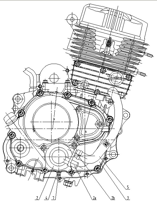
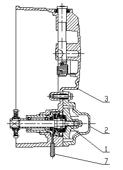
[0025] Such as figure 1 , figure 2 Shown, the present invention has water pump and right crank case cover 3 two major parts, and wherein water pump is made of impeller assembly 1 and water pump cover 2. A positioning hole is provided in the middle of the lower part of the right crankcase cover 3, and the impeller assembly 1 is installed at the positioning hole. The impeller assembly 1 includes components such as an impeller, a water pump shaft, a transmission gear, a bearing, a sealing ring, and the connection relationship of each component. It is the same as the prior art and will not be repeated here. The transmission gear in the impeller assembly 1 meshes with the clutch driven gear, and the clutch driven gear drives the water pump to work. An overflow pipe 7 is installed at the bottom of the right crankcase cover 3, and the overflow pipe 7 communicat...


PUM


Abstract

The invention discloses a water-cooled motorcycle water pump installation structure. A positioning hole is arranged at the middle position of the lower part of the right crankcase cover (3), and an impeller assembly (1) is installed at the positioning hole, and a The water pump cover (2), the water pump cover (2) is fixedly connected with the right crankcase cover (3), the water inlet nozzle (2a) and the water outlet nozzle (2b) are arranged on the water pump cover (2), and the water pump cover ( 2) There is a water cavity (2c) on the inner wall, the water cavity (2c) is involute from small to large, the inner hole of the water inlet (2a) is connected with the small end of the water cavity (2c), The inner hole of the water outlet (2b) communicates with the large end of the water chamber (2c). By changing the installation position of the water pump and the structure of the water pump cover, the present invention can avoid the situation of water and oil communication caused by the intersection of the overflow pipe and the horizontal oil passage hole, prevent water leakage from the water nozzle, effectively increase the pumping water volume, and ensure the smoothness of the engine. Water cooling effect.

Description

technical field [0001] The invention belongs to the technical field of motorcycles, and in particular relates to an installation structure of a water-cooled motorcycle water pump. Background technique [0002] The water pump is an important part of the water circulation cooling system of the water-cooled motorcycle. The water-cooled motorcycle is provided with a cooling water tank, and the water in the cooling water tank is pumped into the engine cylinder through a water pump for cooling cycle, and then returns to the cooling water tank to complete a water circulation cooling process. Such as Figure 6 , Figure 7 As shown, the water pump is installed on the upper right part of the right crankcase cover 3, consists of two parts, the impeller assembly 1 and the water pump cover 2, and is driven to work by the clutch driving gear. The water inlet nozzle 2a of the water pump is located on the water pump cover 2, and the water outlet nozzle 2b is located on the right crankcase...

Claims


Application Information

Patent Timeline
IPC IPC(8): F01P5/10F02F7/00F04D29/40
Inventor 王胜华
Owner 力帆科技(集团)股份有限公司
Why Eureka
Try Eureka