
Lens, light source module, photoelectric module and ceiling lamp

An optical module and lens technology, which is applied in the field of lighting, can solve problems such as affecting light effect and lens light interference, and achieve the effect of avoiding affecting light effect

Active Publication Date: 2020-11-20
宁波公牛光电科技有限公司
View PDF6 Cites 1 Cited by
  • Summary
  • Abstract
  • Description
  • Claims
  • Application Information

AI Technical Summary

Problems solved by technology

[0003] Most of the existing ceiling lamps use a lens for each LED light source for light distribution. When the lens installation space is sufficient, the distance between two adjacent lenses is large enough, and the two lenses will not produce light interference. When the installation space of the lens is limited, the distance between two adjacent lenses will be shortened, which will easily cause light interference between two adjacent lenses, thus affecting the light effect

Method used


Image

  • Lens, light source module, photoelectric module and ceiling lamp
  • Lens, light source module, photoelectric module and ceiling lamp
  • Lens, light source module, photoelectric module and ceiling lamp

Examples


Embodiment Construction

[0023] The following will clearly and completely describe the technical solutions in the embodiments of the application with reference to the drawings in the embodiments of the application. Apparently, the described embodiments are only some of the embodiments of the application, not all of them. Based on the embodiments in this application, all other embodiments obtained by persons of ordinary skill in the art without making creative efforts belong to the scope of protection of this application.

[0024] In the description of this application, it is to be understood that the terms "center", "upper", "lower", "front", "rear", "left", "right", "vertical", "horizontal", The orientations or positional relationships indicated by "top", "bottom", "inner", "outer", etc. are based on the orientations or positional relationships shown in the drawings, and are only for the convenience of describing the application and simplifying the description, rather than indicating or implying Refe...


PUM

PropertyMeasurementUnit
heightaaaaaaaaaa
heightaaaaaaaaaa

Abstract

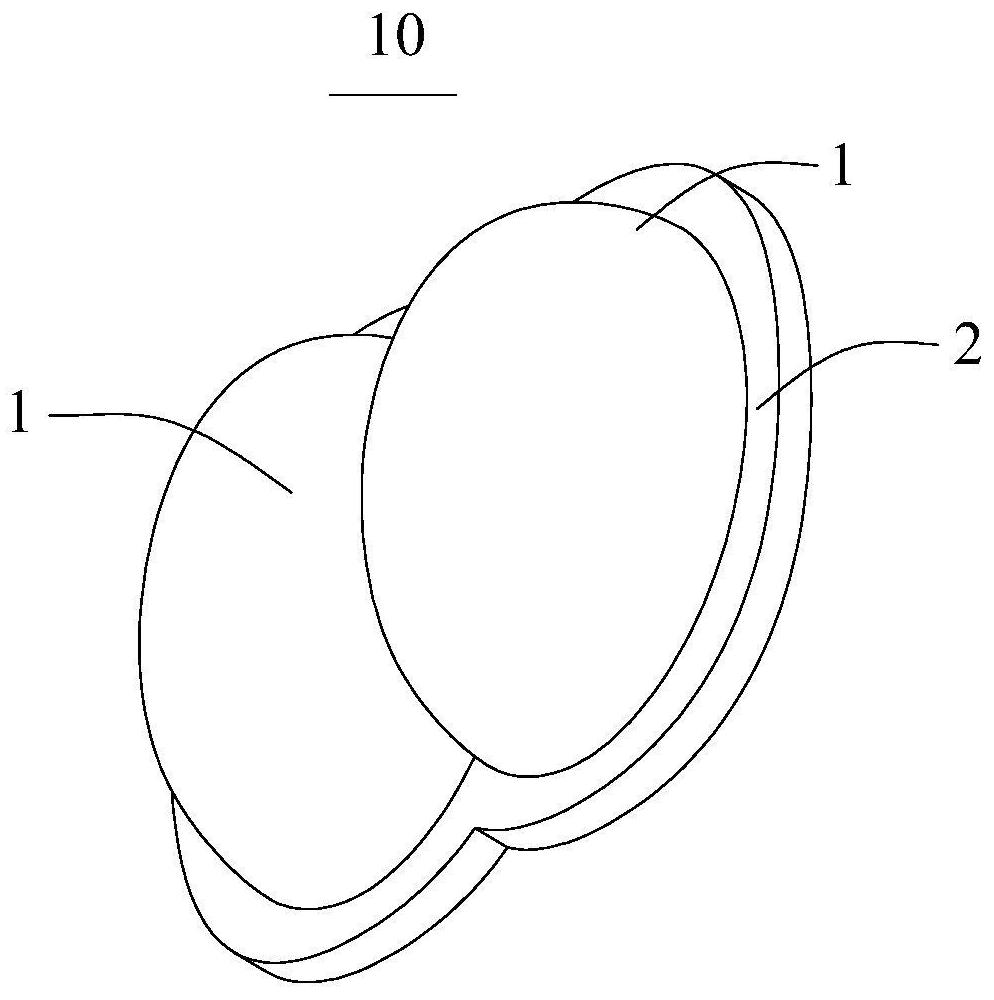
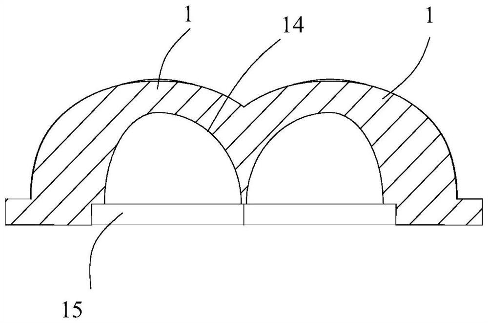
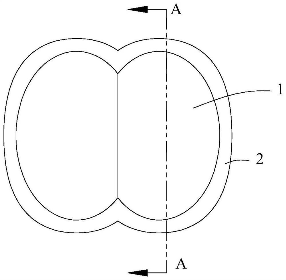
The invention discloses a lens, a light source module, a photoelectric module and a ceiling lamp and relates to the technical field of lighting. By means of the provided lens, installation space of the lens can be saved, and thus the situation that the lighting effect is influenced because light interference is generated is prevented from occurring. The lens comprises two lens units. Each lens unit comprises an installation surface and an irradiation-exiting surface which are oppositely arranged. The middle of each installation surface is sunken towards the direction of the irradiation-exitingsurface, and a cavity is formed. The wall surface of each cavity is the incident plane. The outline of projection, on the plane which the corresponding installation surface is located, of each incident plane comprises a first arc line and a second arc line which are connected into a closed loop structure and whose openings are opposite. The dimension, in the direction perpendicular to the centralsurface, of each second arc line is larger than that, in the direction perpendicular to the central surface by the first arc line. Each second arc line is arranged in a manner that the second arc line is close to the central plane of the lens body. Besides, the two lens units are integrally formed. The light source module, the photoelectric module and the ceiling lamp can be used for improving the property of the lens.

Description

technical field [0001] The present application relates to the technical field of lighting, in particular to a lens, a light source module, a photoelectric module and a ceiling lamp. Background technique [0002] In the field of lighting, ceiling lamps are widely used lamps. Because the ceiling lamp emits light through multiple LED light sources arranged inside, and the beam angle of the LED light source is 120°, therefore, without any light distribution, each LED light source will be close to the spherical surface. Light is emitted to the surroundings, and the light emitted by these LED light sources will present a multi-point radial shape with each LED light source as the center. Under normal circumstances, people hope that the entire diffusion cover of the ceiling lamp can emit uniform light, so it is necessary to distribute light to the LED light source. The purpose of light distribution is to change the light propagation direction of the LED light source. Considering t...

Claims


Application Information

Patent Timeline
Patent Type & Authority Applications(China)
IPC IPC(8): F21V5/04F21S8/04F21Y115/10
CPCF21V5/04F21S8/04F21Y2115/10
Inventor 朱俊杰易博刘金花王泽
Owner 宁波公牛光电科技有限公司
Learn More