Hospital environment air disinfection and ventilation equipment
A technology of ambient gas and ventilation equipment, applied in disinfection, mechanical equipment, lighting and heating equipment, etc., can solve the problems that the air cannot be disinfected and sterilized, and carries a large number of germs
- Summary
- Abstract
- Description
- Claims
- Application Information
AI Technical Summary
Problems solved by technology
Method used
Image
Examples
Embodiment 1
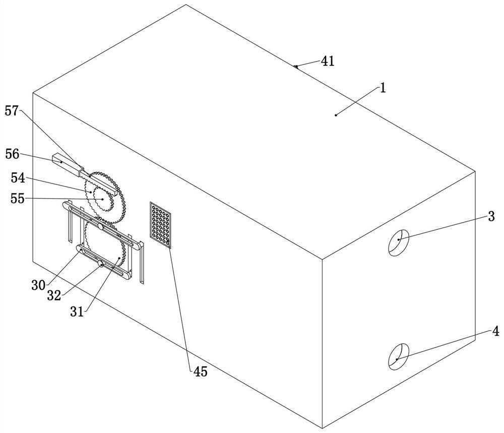
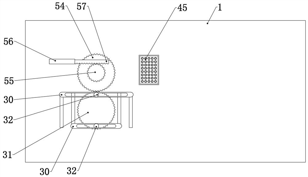
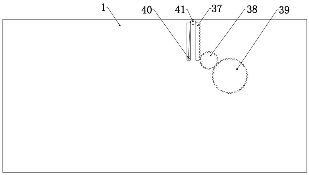
[0039]Embodiment 1, the present invention is a hospital environment gas disinfection and ventilation equipment, which is characterized in that it includes a host 1, and the host 1 is set at one end of the hospital building. Specifically, an equipment room can be independently set at one end of the hospital, and the host 1 is placed In the equipment room, it is convenient for maintenance, and it is also convenient to separate the equipment from circulation personnel and patients. The host 1 is mainly the shell of the host 1, which is used to provide a fixed foundation for the subsequent internal structure. The host 1 is fixedly connected with two Fan 2, the fan 2 is a common fan 2, used for air extraction and exhaust, two fans 2 are fixedly connected in the host 1 at different heights up and down, and the upper air pipe 3 and the lower air pipe 3 are fixedly connected to one side of the host 1 Trachea 4, described upper air pipe 3 communicates with outlet fan 5 fixedly connected...
Embodiment 2
[0048] Embodiment 2, on the basis of Embodiment 1, this embodiment provides a specific structure, so that the upper regulating pipe 8, the lower regulating pipe 9 and the three-way pipe 10 are connected with the upper air pipe 3 and the lower air pipe during the adjustment process. 4 will not leak air at the connection to ensure air tightness, specifically, refer to Figure 5 , Figure 6 , Figure 7 , one end of the two fans 2 is fixedly connected with an internal connecting pipe 15, and one end of the upper fan 2 and the lower fan 2 are fixedly connected with an internal connecting pipe 15 and are connected with the upper regulating pipe 8 and the lower regulating pipe 9 It communicates with the tee pipe 10, and one end of the two inner connecting pipes 15 is slidingly connected with an inner seal ring 16, and the inner wall of the inner seal ring 16 is fixedly connected with a rubber ring to improve the sealing ability. The rings 16 are all connected to the main engine 1 t...
Embodiment 3
[0051] Embodiment 3, on the basis of Embodiment 2, the side of the two fans 2 is provided with a spare fan 22 fixedly connected in the host 1, that is, the upper fan 2 is provided with a spare upper fan 2 and a lower fan 2. There is a spare lower fan 2 next to it. This setting can ensure that the normal ventilation inside the hospital can still be guaranteed during the regular maintenance of the device. The adjacent fan 2 and the spare fan 22 pass through the fan duct 23 and the adjacent inner Connecting pipe 15 is connected, refer to Figure 4 , Fan pipe 23 and two fans 2 are connected with manual valves, which is convenient for maintenance personnel to close and open the air duct.
PUM
 Abstract
Description
Claims
Application Information
 - R&D
- Intellectual Property
- Life Sciences
- Materials
- Tech Scout
- Unparalleled Data Quality
- Higher Quality Content
- 60% Fewer Hallucinations
Browse by: Latest US Patents, China's latest patents, Technical Efficacy Thesaurus, Application Domain, Technology Topic, Popular Technical Reports.
© 2025 PatSnap. All rights reserved.Legal|Privacy policy|Modern Slavery Act Transparency Statement|Sitemap|About US| Contact US: help@patsnap.com


