
Motion conversion device and slicing machine thereof

A conversion device and movement technology, applied in the direction of measuring device, sampling device, sampling, etc., can solve the problems of laborious operation and low production efficiency of structural parts, and achieve the effect of solving laborious operation and improving production efficiency

Pending Publication Date: 2020-11-20
RWD LIFE SCI
View PDF8 Cites 0 Cited by
  • Summary
  • Abstract
  • Description
  • Claims
  • Application Information

AI Technical Summary

Problems solved by technology

[0004] The embodiment of the present invention provides a motion conversion device, which aims to solve the problems of laborious operation and low production efficiency of related structural parts in the prior art when converting the rotary motion of the handwheel into the reciprocating linear motion of the main unit of sample injection

Method used


Image

  • Motion conversion device and slicing machine thereof
  • Motion conversion device and slicing machine thereof
  • Motion conversion device and slicing machine thereof

Examples


Embodiment 1

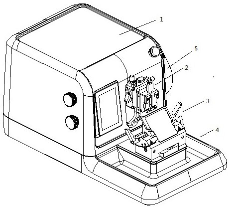
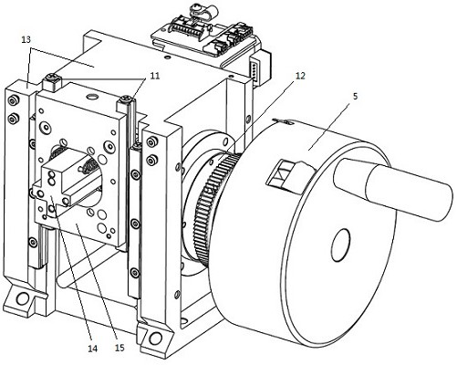
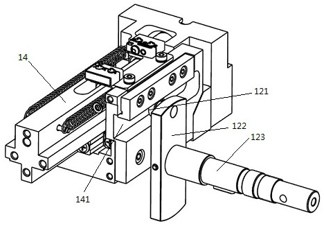
[0021] figure 2 It is a schematic diagram of the motion conversion device provided by the embodiment of the present invention. Such as figure 1 with figure 2 As shown, the motion conversion device includes a guide rail 11 , a drive shaft 12 , a main frame 13 , a sample injection main machine 14 and a slider 15 . The motion conversion device is included in the main body 1 .

[0022] In the embodiment of the present invention, a handwheel 5 is installed at one end of the driving shaft 12 , and the other end passes through the main frame 13 and is connected with the sample injection main machine 14 . Sampling host 14 is connected with main frame 13 by guide rail 11 and slide block 15, and slide block 15 is fixed together with the base (not shown in the figure) in the main frame 13; The position of the sampling host 14 is relatively fixed, that is, the positions of the slider 15 and the sampling host 14 are relatively fixed. A sample positioning device 2 (not shown in the f...

Embodiment 2

[0028] Such as figure 1 with figure 2 As shown, the embodiment of the present invention provides a slicer, including a main body 1 , a sample positioning device 2 , a knife holder 3 , a collection tray 4 and a hand wheel 5 . The main body 1 includes the motion conversion device as described in the first embodiment.

[0029] For the convenience of operation, in the embodiment of the present invention, the hand wheel 5 is arranged at one end of the drive shaft 12 and exposed to the main body 1 .

[0030] In the embodiment of the present invention, the main frame is connected to the main unit of sample injection through guide rails and sliders, and the main unit of sampling injection is connected to the drive shaft through chute and ring, so that the rotational motion of the drive shaft is converted into the reciprocation of the main unit of sampling injection. Linear motion; and the cooperation between the chute and the ring has low requirements on the processing technology a...


PUM


Abstract

The embodiment of the invention provides a motion conversion device. The motion conversion device comprises a guide rail (11), a slider (15), a main frame (13), a sample injection main machine (14) isconnected with the main frame (13) through the guide rail (11) and the slider (15), and a driving shaft (12) connected with the sample injection main machine (14). The sample injection main machine (14) comprises a sliding chute (141), the driving shaft (12) comprises a circular ring, and the circular ring is arranged in the sliding chute (141). When the driving shaft (12) rotates, the circular ring rolls in the sliding groove (141) in a reciprocating mode, and the sample injection main machine (14) does reciprocating linear motion under the action of the guide rail (11), the slider (15) andthe driving shaft (12). According to the embodiment of the invention, the main frame is connected with the sample injection main machine through the guide rail, and the sample injection main machine is connected with the driving shaft through the sliding chute and the circular ring, so that the rotary motion of the driving shaft is converted into the reciprocating linear motion of the sample injection main machine.

Description

technical field [0001] The invention relates to the technical field of slicers, in particular to a motion conversion device and a slicer. Background technique [0002] The rotary microtome is suitable for the production of thin paraffin sections in the fields of biology, medicine and industrial research. Such as figure 1 As shown, a rotary microtome generally includes a main body 1 , a sample positioning device 2 , a knife holder 3 , a collection tray 4 and a hand wheel 5 . The paraffin block embedded with the tissue sample is fixed on the sample positioning device 2 , and the paraffin block can be sliced ​​through the sample feeding mechanism in the main body 1 , the sample positioning device 2 and the knife holder 3 . [0003] During the slicing process, the operator drives the sample feeding mechanism and the sample positioning device 2 in the main body 1 to move up and down by turning the hand wheel 5 to perform slicing. Such a mechanical driving method needs to conve...

Claims


Application Information

Patent Timeline
Patent Type & Authority Applications(China)
IPC IPC(8): G01N1/06
CPCG01N1/06G01N2001/066
Inventor 苏良杰
Owner RWD LIFE SCI
Learn More