
Large squint medium-high orbit SAR two-dimensional beam scanning method

A technology of beam scanning and medium and high orbits, which is applied in the direction of radio wave measurement system, radio wave reflection/reradiation, instruments, etc., and can solve the problems of large amount of SAR echo data and insufficient surveying and mapping bandwidth

Active Publication Date: 2020-11-20
XIDIAN UNIV
View PDF8 Cites 3 Cited by
  • Summary
  • Abstract
  • Description
  • Claims
  • Application Information

AI Technical Summary

Problems solved by technology

[0005] The traditional rotating center beam scanning method used at this stage has the problem of large amount of SAR echo data and insufficient surveying and mapping bandwidth

Method used


Image

  • Large squint medium-high orbit SAR two-dimensional beam scanning method
  • Large squint medium-high orbit SAR two-dimensional beam scanning method
  • Large squint medium-high orbit SAR two-dimensional beam scanning method

Examples


Embodiment 1

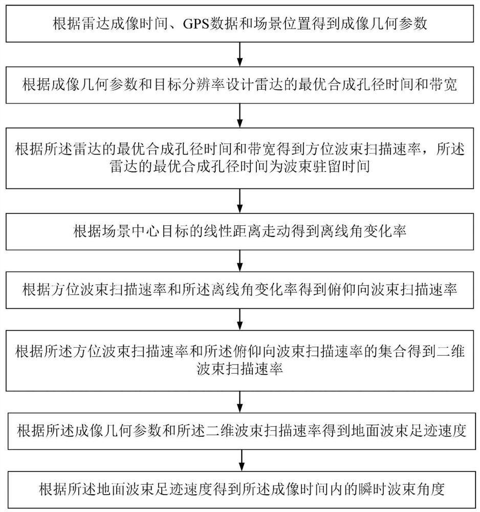
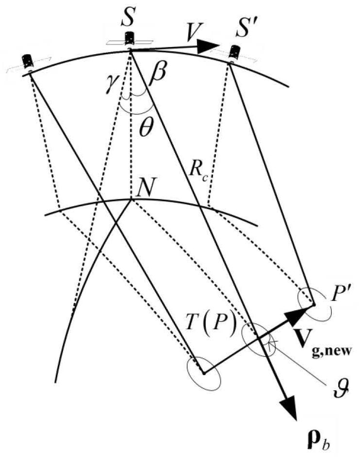
[0049] See figure 1 and figure 2 , figure 1 It is a flow chart of a two-dimensional beam scanning method for SAR with high squint and medium-high orbit provided by the embodiment of the present invention, figure 2 It is a schematic diagram of a TDBS method proposed for mid-high orbit SAR provided by an embodiment of the present invention. An embodiment of the present invention provides a two-dimensional beam scanning method for SAR with high squint and high orbit, including:

[0050] Step 1. Obtain imaging geometric parameters according to radar imaging time, GPS data and scene position.

[0051] Further, the imaging geometric parameters include: the motion parameters of the satellite and the beam vector at the center moment.

[0052] In this embodiment, two-dimensional beam scanning is referred to as TDBS (Two Dimensional beam scanning). The motion parameters of the satellite include: position, velocity and acceleration; the beam vector at the central moment is the bea...

Embodiment 2

[0103] In order to verify the effectiveness of the two-dimensional beam scanning method for SAR with large squint and high orbit SAR provided by the present invention, the following simulation experiments can be used to illustrate.

[0104] See Figure 5 , Figure 5 It is a schematic diagram of a satellite position and a simulated imaging scene provided by an embodiment of the present invention. The simulation is carried out at an orbital altitude of 15,000 kilometers, and the imaging position is selected at a latitude of 90° with the largest orbital curvature. The large squint mode is designed with a resolution of 2m, and the scene width is 80 kilometers.

[0105] See Figure 6a , Figure 6a is the target distance migration obtained by using the traditional rotating center beam scanning method under the condition of constant PRF provided by the embodiment of the present invention. Due to the change of walking distance and center distance, the distance length of SAR echo d...


PUM


Abstract

The invention discloses a large squint medium-high orbit SAR two-dimensional beam scanning method. Firstly, imaging geometric parameters are obtained through radar imaging time, GPS data and scene positions; the optimal synthetic aperture time and bandwidth of a radar are obtained by combining imaging geometry and target resolution design; an azimuth beam scanning rate is obtained according to theoptimal synthetic aperture time and bandwidth of the radar; an offline angle change rate is obtained through linear distance walking of a scene center target; a pitching beam scanning rate is obtained according to the azimuth beam scanning rate and the offline angle change rate; a ground beam footprint speed is calculated by using satellite motion parameters and a two-dimensional beam scanning rate in the imaging geometric parameters; and an instantaneous beam footprint position is determined according to the ground beam footprint speed, and an instantaneous beam pointing direction in the imaging time of the radar is further determined. According to the SAR two-dimensional beam scanning method, the required azimuth resolution can be obtained, and the larger surveying and mapping band width can be determined in a squint mode, or the echo length can be shortened, and the data volume can be reduced.

Description

technical field [0001] The invention belongs to the field of space-borne synthetic aperture radar imaging, and in particular relates to a two-dimensional beam scanning method for high-squint mid-high orbit SAR. Background technique [0002] SAR (Synthetic Aperture Radar, Synthetic Aperture Radar) is an active earth observation system that can be installed on flight platforms such as airplanes, satellites or spacecraft to observe the earth's surface all-weather and all-weather. Surface penetration capability. Therefore, the SAR system has unique advantages in the application of disaster monitoring, environmental monitoring, ocean monitoring, resource exploration, crop yield estimation, surveying and mapping, and military affairs. [0003] SAR observation targets usually require the sensor to work in the squint mode, and for medium and high orbit SAR, the serious distance walking may be as high as hundreds of kilometers, and the line of sight slant distance may also change si...

Claims


Application Information

Patent Timeline
IPC IPC(8): G01S13/90
CPCG01S13/9041
Inventor 孙光才李航刘文康
Owner XIDIAN UNIV
Learn More