
Forward-looking array SAR echo sparse acquisition and three-dimensional imaging method

A technology of three-dimensional imaging and echo, which is applied in radio wave measurement system, radio wave reflection/re-radiation, utilization of re-radiation, etc., can solve the problem of reducing echo data volume, huge data volume, increasing the complexity of system transceiver components and cost and other issues, to achieve the effect of reducing system cost and complexity, reducing the receiving sampling rate and the amount of echo data

Active Publication Date: 2015-12-09
中国人民解放军西安通信学院
View PDF4 Cites 15 Cited by
  • Summary
  • Abstract
  • Description
  • Claims
  • Application Information

AI Technical Summary

Problems solved by technology

At present, the high-resolution forward-looking array SAR 3D imaging system is facing the following problems: (1) The large signal bandwidth increases the complexity and cost of the system's transceiver components, and the current hardware level is also difficult to meet the requirements of the system's ultra-high range resolution. How to synthesize a high-resolution signal with a large bandwidth from an instantaneous small-bandwidth signal? (2) If the system meets the Nyquist sampling requirements, the three-dimensional high resolution will lead to a huge amount of data in the system, which will put a lot of pressure on storage, transmission and processing. How to use the sparseness of the observation scene to reduce the amount of echo data?
[0006] Since the sparse characteristics of the forward-looking array SAR in the cross-course and along-course directions are related to the scattering characteristics and terrain fluctuations of the actual ground scene, the above two methods cannot form a universally applicable sparse acquisition scheme.
Moreover, the optimal sparse characteristic of the forward-looking array SAR is not in the cross-course or along-course direction, and the sparse sampling effect of the above two methods is very limited

Method used


Image

  • Forward-looking array SAR echo sparse acquisition and three-dimensional imaging method
  • Forward-looking array SAR echo sparse acquisition and three-dimensional imaging method
  • Forward-looking array SAR echo sparse acquisition and three-dimensional imaging method

Examples


Embodiment Construction

[0031] In order to make the technical solutions and advantages of the present invention clearer, the present invention will be further described below in conjunction with specific embodiments and accompanying drawings.

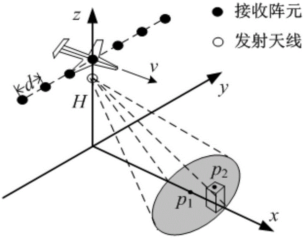
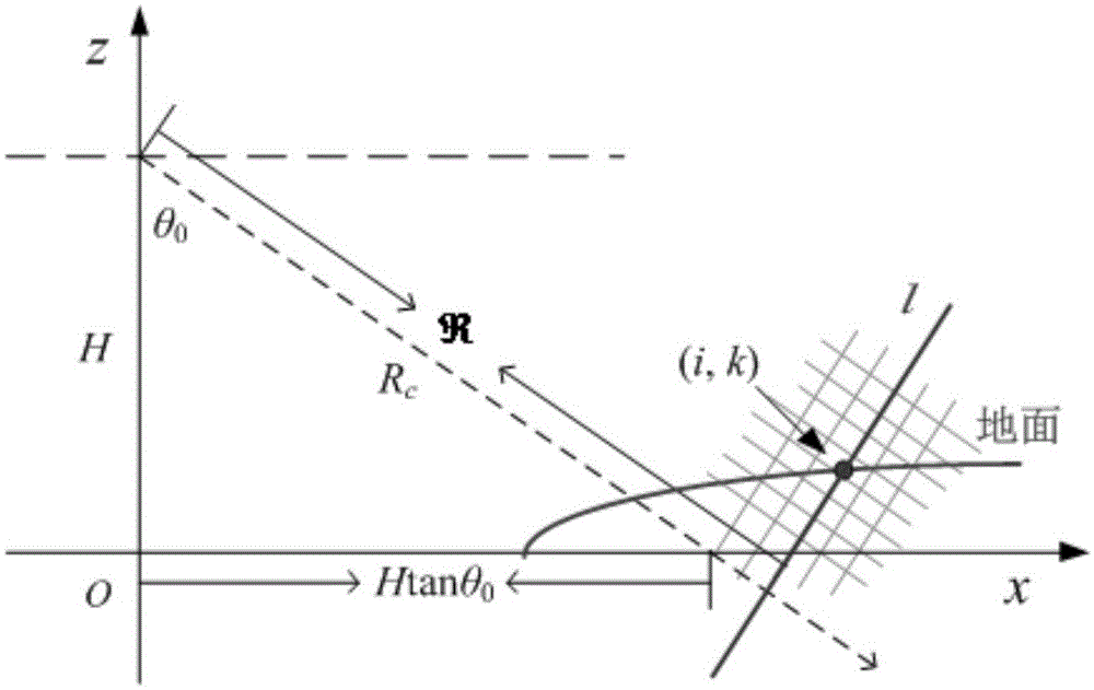
[0032] figure 1 A schematic diagram of the forward-looking array SAR system for earth observation is given. The carrier plane flies horizontally and uniformly in a certain direction at a height H above the observation strip, and the speed is v. The receiving array antennas are arranged horizontally and evenly perpendicular to the flight direction of the platform, the array element interval is d, and the number of array elements is N, then the array length is L=Nd. The transmitting antenna is located at δh directly below the center of the receiving antenna array, and the transmitting beam points forward and downward. The elevation and azimuth angles of the transmit beam center are φ and Define the flight direction of the carrier aircraft as along the headin...


PUM


Abstract

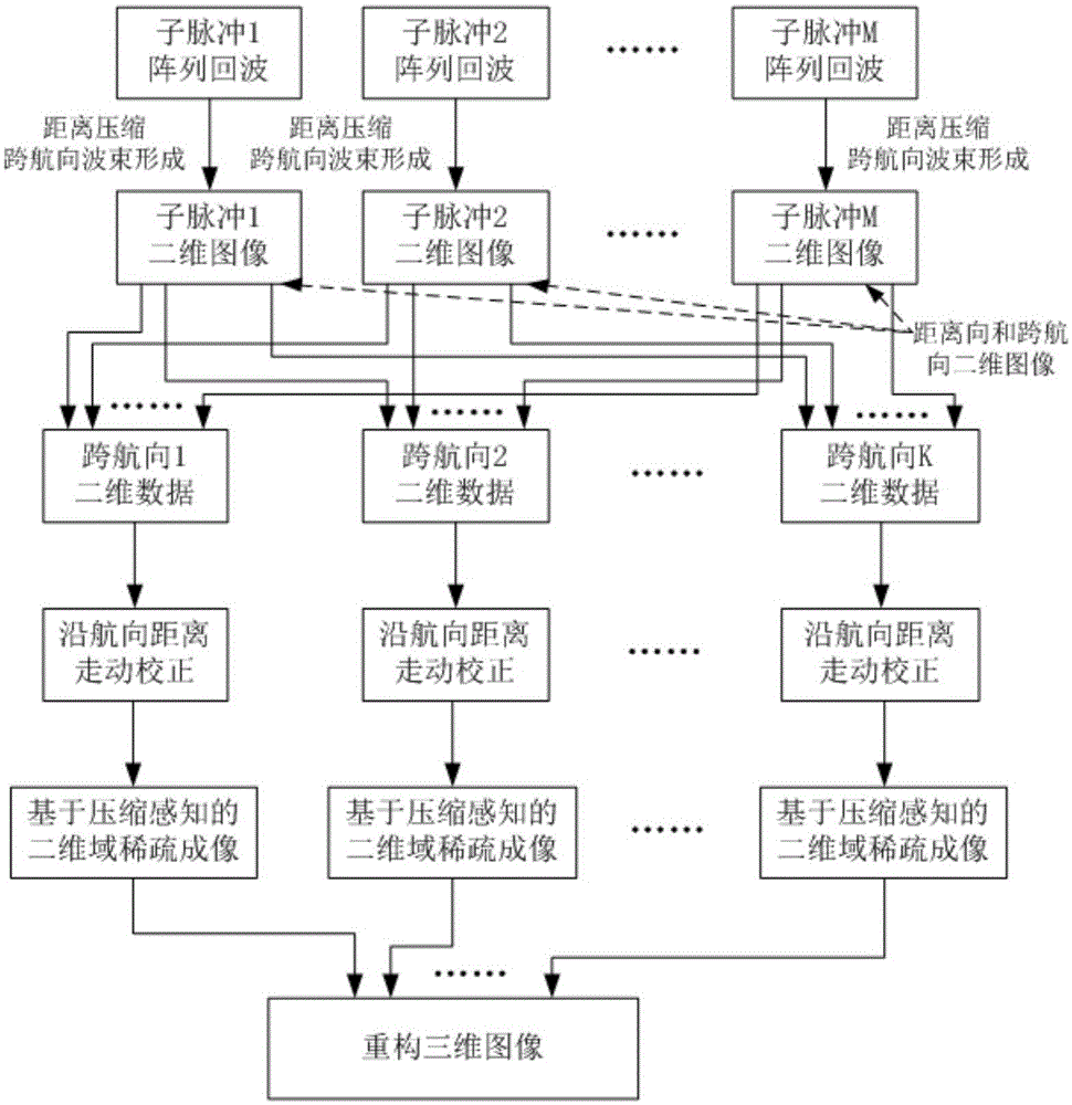
The invention discloses a forward-looking array SAR echo sparse acquisition and three-dimensional imaging method. The method comprises steps: 1, echo signal sparse features are used for optimizing a system transmission mode; 2, small-bandwidth signals are transmitted according to optimized parameters, and ground scattering echoes are received; 3, according to a course order, two-dimensional imaging treatment is carried out on a received scattering echo for each pulse; 4; range walk correction along the course is carried out; 5, echo data for each range gate along the course are arranged into echo vectors, and reconstruction of a scattering source scattering coefficient is realized through compressed sensing algorithm; and 6, the reconstructed scattering coefficient is positioned to the three-dimensional position, and reconstruction of a three-dimensional image is realized. the receiving sampling rate and the echo data amount of the forward-looking array SAR system are significantly reduced, the cost and the complexity of the system are thus reduced, and a new solution is provided for design and realization of the forward-looking array SAR system; and in addition, the method avoids the range migration correction problem when the compressed sensing technology is used for realizing ground scattering source sparse reconstruction.

Description

technical field [0001] The invention belongs to the field of radar data acquisition and signal processing, and particularly relates to signal acquisition and three-dimensional imaging of low sampling rate and small data volume of high-resolution forward-looking array SAR, and is generally applicable to three-dimensional observation of scenes directly ahead on low-altitude short-distance platforms. Background technique [0002] In the field of radar three-dimensional imaging, forward-looking array SAR has attracted the attention and research of many scientific research institutions and scholars in recent years. It is suitable for low-altitude and close-range earth observation of high-frequency band (such as millimeter wave) radar, and has the advantage of obtaining three-dimensional images of the observation scene in front of and below the platform in near real-time. A new way to work 24 / 7. Forward-looking array SAR adopts matched filtering of broadband transmission signals ...

Claims


Application Information

Patent Timeline
IPC IPC(8): G01S13/90
CPCG01S13/904G01S13/9043
Inventor 刘向阳孟进赵海燕刘伟赵洪钢牛德智杜宇扬
Owner 中国人民解放军西安通信学院
Learn More