A continuous stamping die for winding stator core

A technology for stamping dies and stator iron cores, which is used in the manufacture of stator/rotor bodies, etc., can solve the problems of reducing the production efficiency of stator iron cores, discontinuous production process, etc., and achieves a simple structure, high adaptability, and guaranteed product quality. Effect

Active Publication Date: 2021-07-09
台州市扬诺模具有限公司
View PDF1 Cites 0 Cited by
  • Summary
  • Abstract
  • Description
  • Claims
  • Application Information

AI Technical Summary

Problems solved by technology

[0004] When producing the above-mentioned stator core, it is usually necessary to carry the iron core strip multiple times, and use multiple equipment and molds to punch out features such as mounting holes and deformation grooves on the iron core strip. The production process is discontinuous, which reduces the stator iron core. Core production efficiency needs to be improved

Method used


Image

  • A continuous stamping die for winding stator core
  • A continuous stamping die for winding stator core
  • A continuous stamping die for winding stator core

Examples


Embodiment 1

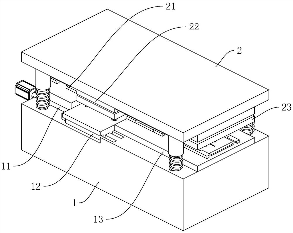
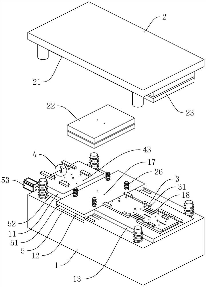
[0040] Embodiment 1: as figure 1 , figure 2 As shown, a continuous stamping die for a winding stator core includes a lower template 1 and an upper template 2, and the lower template 1 is sequentially provided with a first fixed mold 11, a second fixed mold 12 and a third fixed mold 13, A first movable mold 21 , a second movable mold 22 and a third movable mold 23 are sequentially arranged on the upper template 2 .

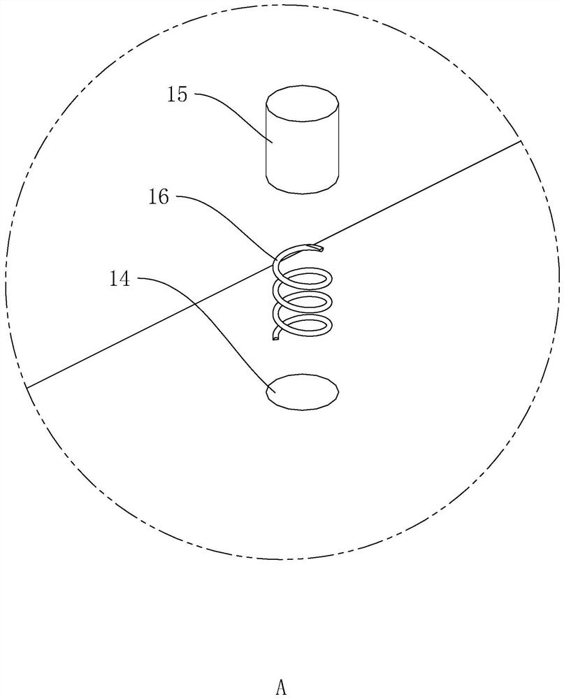
[0041] Such as figure 2 , image 3 As shown, the upper end surfaces of the first fixed mold 11, the second fixed mold 12 and the third fixed mold 13 are distributed with a plurality of sliding holes 14, and the sliding holes 14 are vertically slidably connected with sliding rods for contacting the lower end surface of the iron core band. 15, and a spring 16 is provided between the lower end surface of the sliding rod 15 and the bottom wall of the sliding hole 14.

[0042] Such as figure 2 , Figure 4 As shown, the first movable mold 21 , the second movable...

Embodiment 2

[0053] Embodiment 2: as Figure 5 As shown, the difference from Embodiment 1 is that a support 6 is provided at one end of the lower formwork 1 close to the third fixed form 13 , and a support base 61 is horizontally provided on the support 6 . A cleaning box 7, a flushing box 8, and a drying box 9 are sequentially arranged on the support base 61, and the outer walls of the upper ends of the cleaning box 7, the washing box 8, and the drying box 9 are all provided with through holes 62 for passing through the iron core belt. .

[0054] After the iron core strip is stamped and formed, the iron core strip is usually directly wound to ensure continuous production and processing of the stator iron core. Therefore, after the iron core band is formed, use the cleaning box 7 to clean the impurities on the surface of the iron core band, then use the flushing box 8 to rinse the cleaning solution, and finally use the drying box 9 to dry the water stains on the surface of the iron core b...


PUM


Abstract

The application discloses a continuous stamping die for a wound stator core, which relates to the field of motor stators, and includes a lower template and an upper template, and the lower template is sequentially provided with a first fixed mold, a second fixed mold and a third fixed mold , the first movable mold, the second movable mold and the third movable mold are arranged in sequence on the upper template; the lower end surface of the second movable mold is provided with the first punching knife for punching the mounting hole, There are first punching grooves for the first punching knives to be embedded in, a plurality of second punching knives are arranged on the lower surface of the third movable die, and a plurality of second punching grooves for the second punching knives to be respectively embedded in are arranged on the third fixed die. The application has the following advantages and effects: by setting a high-continuity stamping die, the continuous positioning, stable transmission and automatic punching and punching operations of the iron core strip are realized, and the contact forming and rapid stamping forming of the stator core are realized, ensuring the process continuity, thereby improving the production efficiency of the stator core.

Description

technical field [0001] The present application relates to the field of motor stators, in particular to a continuous stamping die for winding stator cores. Background technique [0002] The motor refers to an electromagnetic device that realizes the conversion or transmission of electric energy according to the law of electromagnetic induction. The motor is mainly composed of a stator and a rotor. During the production and processing of the stator, in order to save the waste of materials, winding stator cores are usually produced. [0003] Chinese patent CN207382071U discloses a coiled motor stator core, which includes a core body formed by pressing a spirally wound core strip. The core body includes a pole shoe for winding a metal wire and a The ring-shaped yoke that fixes the pole piece is further provided with a reinforcing part radially on the inner circumference of the yoke, and a plurality of mounting holes and deformation grooves are opened on the reinforcing part. ...

Claims


Application Information

Patent Timeline
Patent Type & Authority Patents(China)
IPC IPC(8): H02K15/02
CPCH02K15/02
Inventor 徐富强
Owner 台州市扬诺模具有限公司
Why Eureka
Try Eureka