Prosthetic heart valve with pouch

A valve and capsule technology, applied in the field of artificial valves and valve substitutes, can solve problems such as reduced cardiac output, ventricular weakening, and atrial volume overload

Pending Publication Date: 2020-11-20
CARDIOVALVE LTD
View PDF7 Cites 0 Cited by
  • Summary
  • Abstract
  • Description
  • Claims
  • Application Information

AI Technical Summary

Problems solved by technology

Reverse flow of blood from the ventricles into the atria leads to an increase in total stroke volume and a decrease in cardiac output, resulting in volume overload and pressure overload of the atria, which eventually leads to weakening of the ventricles

Method used


Image

  • Prosthetic heart valve with pouch
  • Prosthetic heart valve with pouch
  • Prosthetic heart valve with pouch

Examples


Embodiment Construction

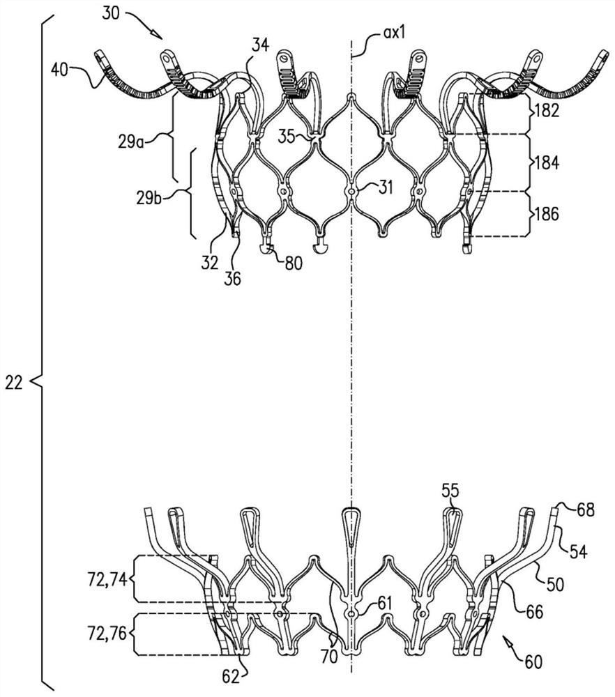
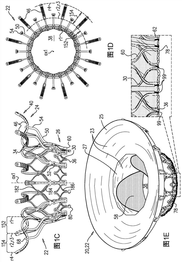
[0085] refer to Figures 1A to 1E and figure 2 , the above is a schematic diagram of an implant 20 and a stent assembly 22 of the implant according to some applications of the present invention. Implant 20 acts as an artificial valve for a native heart valve, typically a mitral valve, for a subject. Implant 20 has a compressed state for minimally invasive (typically transluminal, e.g., femoral) delivery, and an expanded state into which the native heart valve begins to be transitioned, and in the expanded state In, the implant provides prosthetic heart valve function. Implant 20 includes stent assembly 22 , elastic sheet 23 and a valve component, such as artificial leaflet 58 .

[0086] Figure 1A to Figure 1E The implant 20 and stent composite configuration 22 are shown in the expanded state. For clarity, Figures 1A to 1D The stent assembly configuration 22 is shown separately. Figure 1A an exploded isometric view showing the stent assembly 22, and Figure 1B A side...


PUM


Abstract

A valve body (32) circumscribes a longitudinal axis and defines a lumen along the axis. Upstream arms (46) are coupled to the valve body, and extend radially outward from the valve body to respectivearm-tips. Downstream legs (50) are coupled to the valve body, and extend radially outward from the valve body and toward the plurality of arms. A flexible pouch (490) extends radially outward from thevalve body. The arms and the legs narrow the pouch therebetween to form a narrowed portion of the pouch, thereby defining, in an interior space of the pouch: (a) an inner portion (502), radially inward from the narrowed portion, and in fluid communication with the lumen, and (b) an outer portion (504), radially outward from the narrowed portion, and in fluid communication with the inner portion via the narrowed portion.

Description

[0001] Cross References to Related Applications [0002] This application claims priority from the following applications: [0003] U.S. Patent Application No. 15 / 956,956, filed April 19, 2018, by Iamberger et al., entitled "Prosthetic Heart Valves"; [0004] International Patent Application No. PCT / IL2018 / 050725 entitled "Prosthetic Heart Valve" filed by Hariton et al. on July 4, 2018; [0005] U.S. Patent Application No. 16 / 135,969, filed September 19, 2018, by Hariton et al., entitled "Prosthetic Valve Having an Expandable Annulus Configured to Expand Radially"; and [0006] US Patent Application Serial No. 16 / 135,979, filed September 19, 2018, by Hariton et al., entitled "Prosthetic Valve Having an Inflatable Annulus Configured to Fill the Space Between Atrial and Ventricular Tissue Anchors." [0007] All of the above applications are incorporated herein by reference. technical field [0008] Some applications of the invention relate generally to valve replacements. Mo...

Claims


Application Information

Patent Timeline
Patent Type & Authority Applications(China)
IPC IPC(8): A61F2/24
CPCA61F2/2409A61F2/2418A61F2230/0054A61F2230/0052A61F2250/0069A61F2250/0003A61F2220/0075A61F2/2436
Inventor 伊利亚·哈里顿梅尼·伊姆伯格伊莲娜·卡西莫夫波阿斯·哈拉里艾维瑞姆·鲍姆
Owner CARDIOVALVE LTD
Why Eureka
Try Eureka