
A double-layer wind resistance braking device, a double-layer driver's cab structure and a high-speed train

A technology for wind resistance braking and high-speed trains, which is applied to the operating mechanism, braking components, and locomotives of railway vehicle brakes, and can solve the problems of inability to meet the braking needs of high-speed trains, the train cannot stop, and the braking distance is extended. The effect of solving insufficient braking force, improving aerodynamic resistance and high reliability

Active Publication Date: 2021-11-02
CENT SOUTH UNIV
View PDF4 Cites 0 Cited by
  • Summary
  • Abstract
  • Description
  • Claims
  • Application Information

AI Technical Summary

Problems solved by technology

Traditional train braking methods rely on tread braking, disc braking or regenerative braking depending on the adhesion between the wheels and rails. As the speed of high-speed trains increases, the braking distance will be greatly extended when the train is braking at a speed of 350km / h. The train cannot stop within the traditional braking distance of 350km / h.
[0004] Traditional braking forms can no longer meet the braking needs of high-speed trains under emergency conditions such as earthquakes or train collisions

Method used


Image

  • A double-layer wind resistance braking device, a double-layer driver's cab structure and a high-speed train
  • A double-layer wind resistance braking device, a double-layer driver's cab structure and a high-speed train
  • A double-layer wind resistance braking device, a double-layer driver's cab structure and a high-speed train

Examples


Embodiment Construction

[0026] In order to facilitate the understanding of the present invention, the present invention will be described more fully and in detail below in conjunction with the accompanying drawings and preferred embodiments, but the protection scope of the present invention is not limited to the following specific embodiments. It should be noted that, in the case of no conflict, the embodiments of the present invention and the features in the embodiments can be combined with each other.

[0027] Unless otherwise defined, all technical terms used hereinafter have the same meanings as commonly understood by those skilled in the art. Words such as "one" or "one" used in the specification and claims of the patent application of the present invention do not indicate a limitation of quantity, but indicate that there is at least one. Words such as "connected" or "connected" are not limited to direct connection, but may be indirectly connected through other intermediate connectors. "Up", "D...


PUM


Abstract

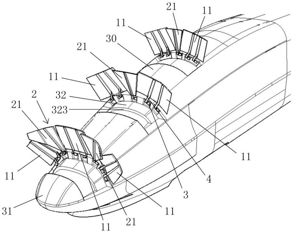
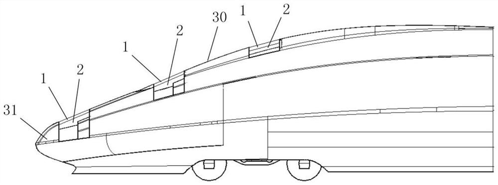
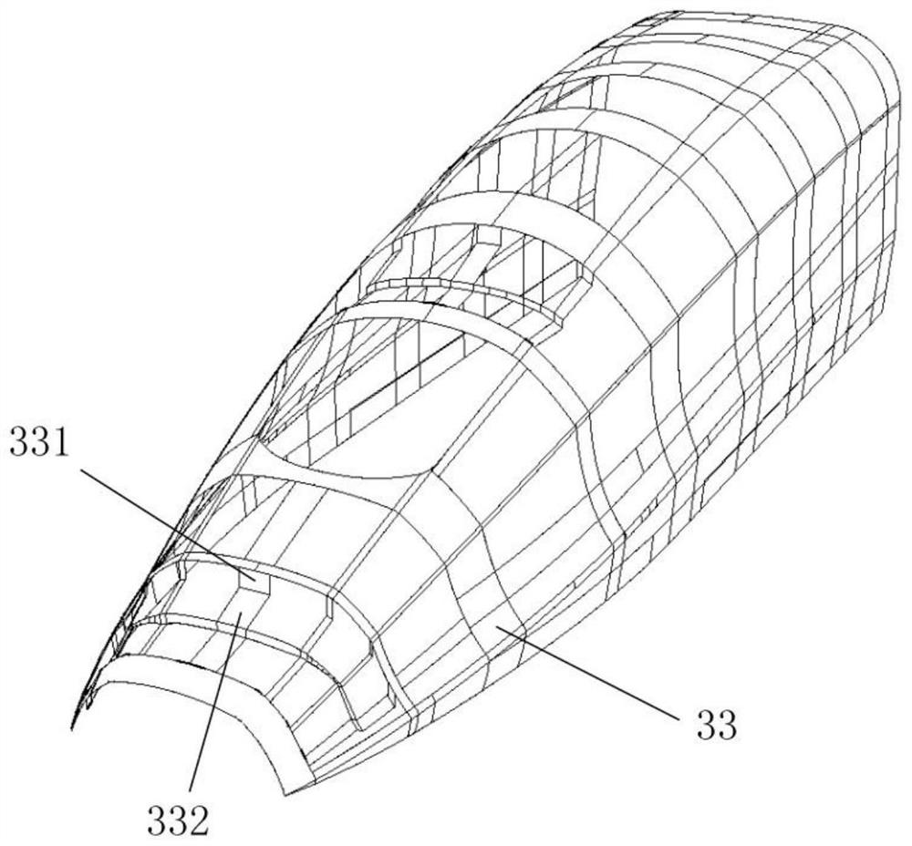
The invention discloses a double-layer wind resistance brake device, a double-layer cab structure and a high-speed train. The double-layer wind resistance brake device includes an outer layer wind resistance brake plate and an inner layer wind resistance brake plate installed in the variable section area of ​​the train. The outer windage braking plate includes a plurality of outer braking unit plates arranged laterally along the outer contour of the variable cross-section area, and the inner layer wind resistance braking plate includes a plurality of inner layer braking unit plates arranged laterally along the outer contour of the variable cross-section area, The opening and closing drive mechanism is installed on the driver's cab of the high-speed train. When the outer layer wind resistance brake plate and the inner layer wind resistance brake plate are opened, the inner layer brake unit plate is located inside the outer layer brake unit plate and is located on the adjacent outer layer brake unit plate. In the gap between the unit boards. The double-layer windage braking device, the double-layer driver's cab structure and the high-speed train have simple structure, convenient installation, and high reliability, which can meet the demand for braking force of the high-speed train under emergency braking and solve the problem of high-speed train braking during emergency braking. The problem of lack of motivation.

Description

technical field [0001] The invention relates to the technical field of rail transit equipment, in particular to a double-layer wind resistance braking device, a double-layer driver's cab structure and a high-speed train. Background technique [0002] When the speed of traditional trains in my country is 120km / h, the air resistance accounts for about 40% of the total resistance; for the speed-up train composed of blunt locomotives pulling speed-up passenger cars (the bottom of the vehicle is exposed), when the speed is 160km / h, the air resistance accounts for about 75% of the total resistance; At 300km / h, air resistance accounts for about 85% of the total resistance. The air resistance of the train is proportional to the square of the train speed. With the increase of the train speed, the air resistance of the train increases rapidly, and the proportion of the air resistance of the train in the total resistance is also increasing. [0003] When the running speed of the high-s...

Claims


Application Information

Patent Timeline
Patent Type & Authority Patents(China)
IPC IPC(8): B61C17/04B61H13/00B61H11/10B60T1/16
CPCB60T1/16B61C17/04B61H11/10B61H13/00
Inventor 高广军张洁姜琛李锋
Owner CENT SOUTH UNIV
Learn More