
Anti-blockage rotary bin

A rotating warehouse and anti-blocking technology, which is applied in the field of warehouses, can solve the problems of poor anti-blocking effect, etc., and achieve the effect of improving stability, flexible rotation, and good anti-blocking effect

Active Publication Date: 2020-11-24
NINGBO FUSHIDA ELECTRIC ENG
View PDF6 Cites 4 Cited by
  • Summary
  • Abstract
  • Description
  • Claims
  • Application Information

AI Technical Summary

Problems solved by technology

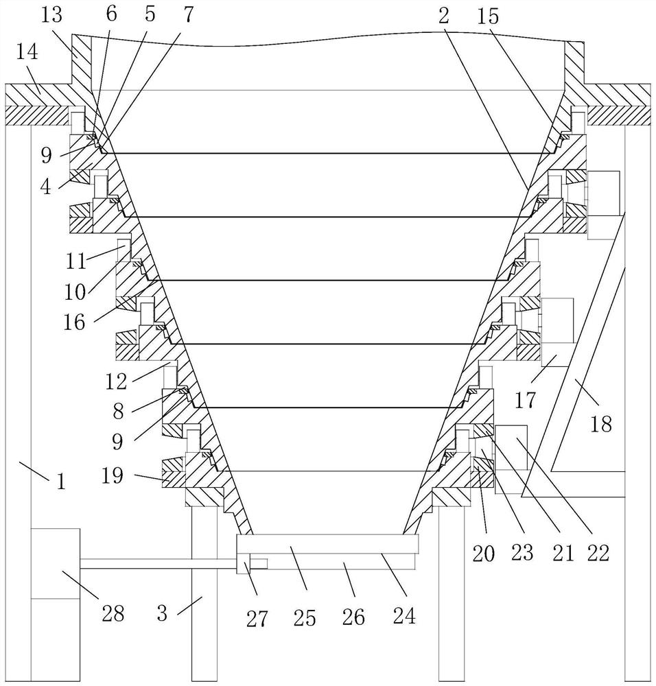
[0003] The purpose of the present invention is to overcome the disadvantages of poor anti-blocking effect of the current silo anti-blocking device, and provide a kind of anti-blocking rotary silo with a conical silo body that has a better anti-blocking effect.

Method used


Image

  • Anti-blockage rotary bin
  • Anti-blockage rotary bin

Examples


Embodiment 1

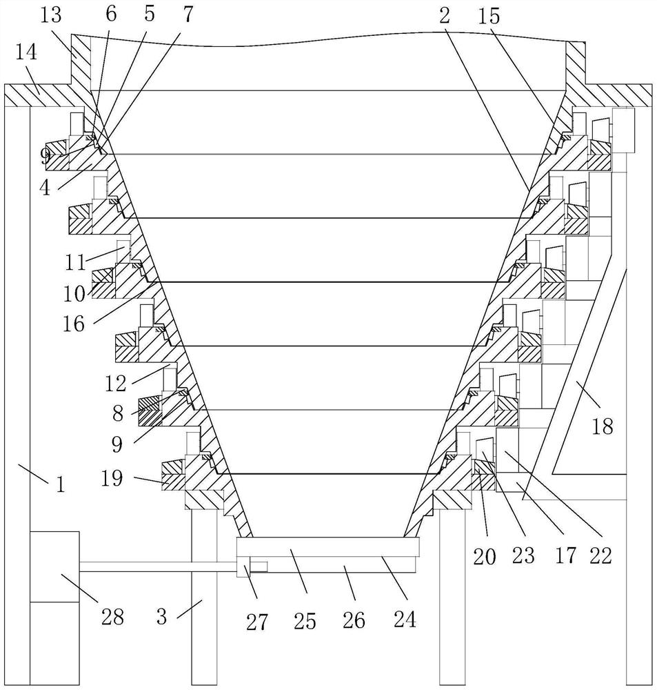
[0018] Embodiment 1, as attached figure 1 Shown: an anti-blocking material rotary bin, including: a cylindrical bin body, a conical bin body with a discharge port at the bottom of the cylindrical bin body, and a discharge gate at the lower end of the conical bin body , the support frame 1 whose upper end is screwed to the cylindrical warehouse body; the conical warehouse body includes: several rotating warehouse bodies provided with frustum-shaped inner sides 2 and pivotally connected up and down in sequence, and the lower end of the last rotating warehouse body screwed together The supporting frame 3 is the driving device for the rotating bin body; the frustum-shaped inner sides 2 of the six rotating bins form the inner side of the conical bin body; the cylindrical bin body is pivotally connected with the uppermost rotating conical bin section.

[0019] The rotating bin body includes: a rotating bin body main body 4, a plurality of tapered rollers 5, a cover ring 6; The body...

Embodiment 2

[0025] Embodiment 2, as attached figure 1 Shown: an anti-blocking material rotary bin, including: a cylindrical bin body, a conical bin body with a discharge port at the bottom of the cylindrical bin body, and a discharge gate at the lower end of the conical bin body , the support frame 1 whose upper end is screwed with the cylindrical warehouse body; the conical warehouse body includes: six rotating warehouse bodies provided with a frustum-shaped inner wall 2 and pivotally connected up and down in sequence, and screwed with the lower end of the bottom rotating warehouse body main body 4 Connected support frame 3, rotating bin body driving device; the frustum-shaped inner sides of the six rotating bins form the inner side of the conical bins; the tubular bins are pivotally connected to the last rotating conical bin section.

[0026] The rotating bin body includes: a rotating bin body main body 4, a plurality of tapered rollers 5, a cover ring 6; The body main body 4 outside i...


PUM


Abstract

The invention relates to an anti-blockage rotary bin which comprises a cylindrical bin body, a conical bin body, a discharge gate and a supporting frame. The conical bin body is disposed on the lowerside of the cylindrical bin body, and a discharge port is disposed at the bottom of the conical bin body. The discharge gate is disposed at the lower end of the conical bin body. The upper end of thesupporting frame is connected with the cylindrical bin body. The conical bin body comprises a plurality of rotary bin bodies, a supporting frame and a rotary bin body driving device, wherein frustum-shaped inner side walls are disposed on the rotary bin bodies, the rotary bin bodies are vertically sequentially in pivot joint, the supporting frame is connected with the lower end of the bottommost rotary bin body, the frustum-shaped inner side walls of the rotary bin bodies form an inner side wall of the conical bin body, and the cylindrical bin body is in pivot joint with the topmost rotary binbody of the conical bin body. In the anti-blockage rotary bin, the conical bin body is good in anti-blockage effect.

Description

technical field [0001] The invention relates to the technical field of warehouses, in particular to an anti-blocking material rotating warehouse. Background technique [0002] The lower part of the silo is often equipped with a conical silo, and the material sticking to the wall can easily cause the conical silo to block the material; the utility model of Chinese patent application number 201921611197.7 discloses a silo anti-blocking device, including a silo, a rotating body, and a rotating body Including the scraper, the silo includes the upper cylindrical silo body and the conical silo body below. The bottom of the conical silo body is provided with a discharge port, and the scraper extends upward from the discharge port along the inner wall of the conical silo. Rotate the connection sleeve at the mouth, the sleeve is covered with a gear ring, the inner wall of the sleeve is fixed to the tail of the scraper, and it also includes a bracket. The bracket includes a top plate ...

Claims


Application Information

Patent Timeline
IPC IPC(8): B65D88/26B65D88/64B65D90/02
CPCB65D88/26B65D88/64B65D90/02
Inventor 衣启坤江黎明
Owner NINGBO FUSHIDA ELECTRIC ENG
Learn More