Central rotary joint, pipe winder and continuous pipe operation equipment

A rotary joint and rotor technology, applied in the direction of pipes/pipe joints/pipe fittings, mechanical equipment, pipes, etc., can solve the problem of large overall volume of the central rotary joint, and achieve the effect of compact main structure and reduced cross-section.

Pending Publication Date: 2020-11-24
HUNAN SHUANGDA ELECTROMECHANICAL CO LTD
View PDF17 Cites 0 Cited by
  • Summary
  • Abstract
  • Description
  • Claims
  • Application Information

AI Technical Summary

Problems solved by technology

[0004] In view of this, the embodiment of the present application expects to provide a central rotary joint, a hose reel and coiled tubing operation equipment to solve the problem of the overall large volume of the central rotary joint

Method used


Image

  • Central rotary joint, pipe winder and continuous pipe operation equipment
  • Central rotary joint, pipe winder and continuous pipe operation equipment
  • Central rotary joint, pipe winder and continuous pipe operation equipment

Examples


Embodiment Construction

[0038] It should be noted that, in the case of no conflict, the embodiments in the application and the technical features in the embodiments can be combined with each other. Undue Limitation of This Application.

[0039] The orientation terms in the description of the present application are only for the convenience of describing the application and simplifying the description, rather than indicating or implying that the device or element referred to must have a specific orientation, be constructed and operated in a specific orientation, and therefore cannot be construed as a reference to the application. limits.

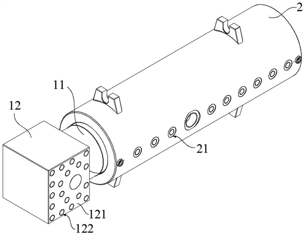
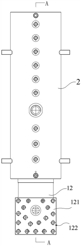
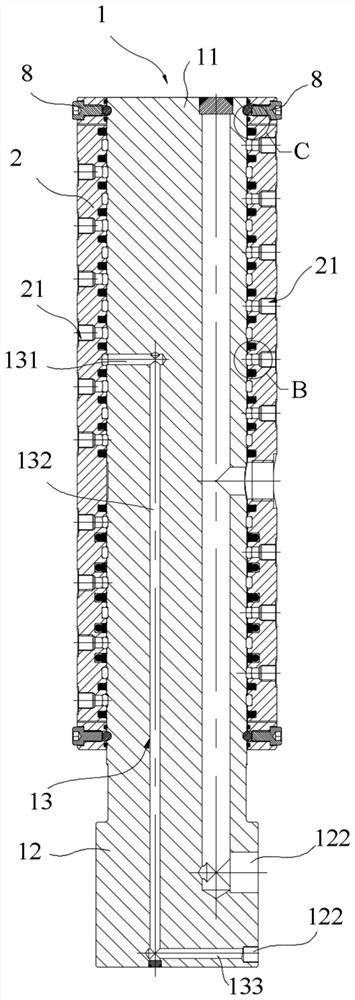
[0040] The first aspect of the embodiment of the present application provides a central rotary joint, please refer to Figure 1 to Figure 9 , including a mandrel 1 and a rotor 2 sleeved on the mandrel 1 . The mandrel 1 includes a socket portion 11 and a mounting portion 12 formed at one end of the socket portion 11. One side of the mounting portion 12 is formed wi...


PUM


Abstract

The invention provides a central rotary joint, a pipe winder and continuous pipe operation equipment. The central rotary joint comprises a mandrel and a rotor. The mandrel comprises a sleeving part and a mounting part formed at one end of the sleeving part, one side of the mounting part is provided with a mounting surface, and a plurality of first liquid ports are formed in the mounting surface. Second liquid ports in one-to-one correspondence with the first liquid ports are formed in the rotor. A plurality of flow channels are formed on the mandrel, a plurality of ring cavities are formed between the sleeving part and the rotor, and each first liquid port communicates with the corresponding ring cavity through the corresponding flow channel. The flow channels comprise the first flow channel, the second flow channel and the third flow channel, and the distance between the axis of at least part of the third flow channel and the axis of the second flow channel communicating with the third flow channel is larger than zero. According to the central rotary joint, the distance between the axis of at least part of the third flow channel and the axis of the second flow channel communicating with the third flow channel is larger than zero, so that the structure of the central rotary joint is more compact, and the installation requirement of all pipelines on the first liquid ports can bemet.

Description

technical field [0001] The present application relates to the technical field of oil production engineering machinery, in particular to a rotary joint, a hose reel and coiled tubing operation equipment. Background technique [0002] In coiled tubing equipment, multiple pipelines are usually connected to a central rotary joint, and the central rotary joint usually includes a mandrel and a rotor that can rotate around the mandrel. The inlet and outlet of the pipeline are respectively connected with the mandrel and the rotor, wherein the pipeline at one end connected with the rotor is wound on the rotor and rotates together with the rotor. [0003] In the prior art, there are as many as 20 pipelines installed on the central rotary joint, thus forming 20 flow channels in the mandrel. In order to facilitate the disassembly of the connecting pipelines, a wrench for disassembling the pipelines needs to be reserved between the flow channels space, so the overall volume of the centr...

Claims


Application Information

Patent Timeline
Patent Type & Authority Applications(China)
IPC IPC(8): F16L41/03F16L27/093B65H75/38B65H75/44
CPCF16L41/03F16L27/093B65H75/38B65H75/44
Inventor 卿丽纯郭方云徐亮许乐平肖久焜
Owner HUNAN SHUANGDA ELECTROMECHANICAL CO LTD
Why Eureka
Try Eureka