
Tractor spring testing fixture
A technology for tractors and inspection tools, which is applied to inspection tools for the symmetry of central bolts to detect the free arc height and half-chord length of tractor springs. High, time-saving and labor-saving detection effect
Patent Information
- Authority / Receiving Office
- CN · China
- Patent Type
- Applications(China)
- Current Assignee / Owner
- Publication Date
- 2020-11-24
- Estimated Expiration
- Not applicable · inactive patent
Smart Images
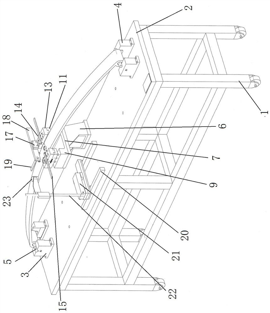
Figure 1 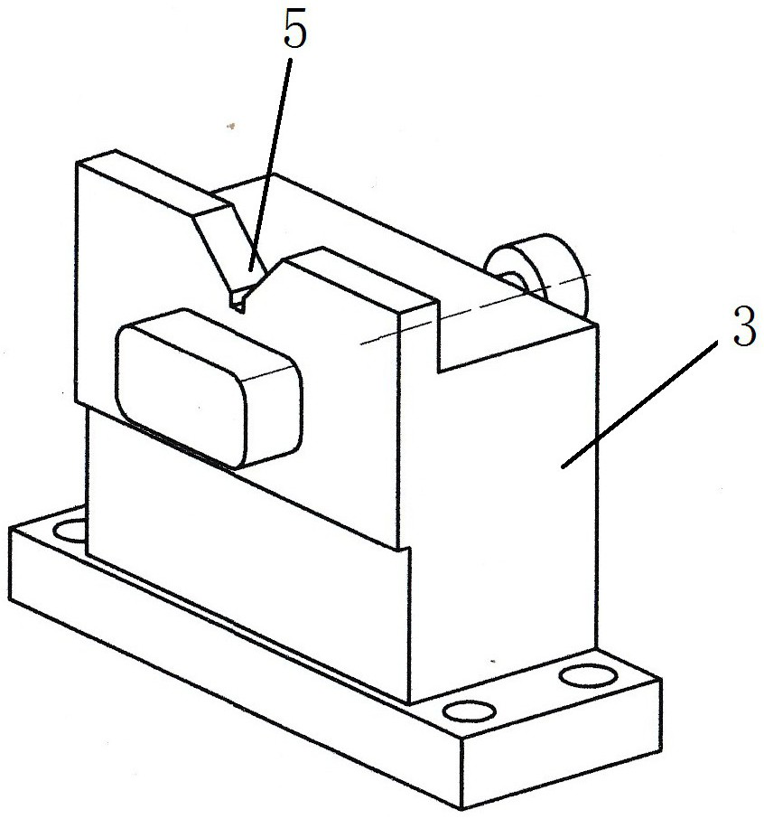
Figure 2 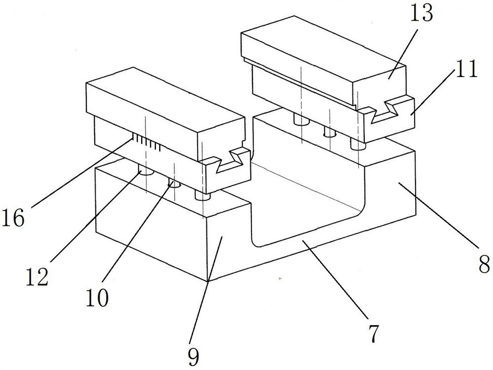
Figure 3
Abstract
Description
Technical field:
[0001] The invention relates to the field of spring inspection tools, in particular to a inspection tool capable of detecting the free arc height, half-chord length and central bolt symmetry of tractor springs. Background technique:
[0002] The detection of the free arc height of the tractor spring is a mandatory item. The current method is generally to measure with a ruler or a tape measure, which has large detection errors, low accuracy, time-consuming and labor-intensive work, and labor-intensive work; the half-chord length value of the tractor spring was previously measured. And the symmetry of the center bolt (that is, whether the center bolt is on the longitudinal centerline of the leaf spring) is not tested, but at present, many users request to detect the value of the half-chord length and the symmetry of the center bolt, so it is urgent to design a device that can simultaneously Checking tools for testing tractor spring free arc height, half chord ...
Examples
Embodiment Construction
[0019] Combine below Figure 1-3 The present invention is further described;
[0020] It includes a bracket 1, a base plate 2 fixed on the top of the bracket, two fixed end base blocks 3 are fixed on the upper surface of the base plate, and two movable end base blocks 4 are fixed on the right portion of the upper surface of the base plate; the two fixed end bases Both the block and the two movable end blocks are arranged one behind the other;
[0021] The upper surfaces of the two fixed-end base blocks are provided with V-shaped grooves 5 extending downward, and the two fixed-end base blocks directly below the V-shaped grooves are provided with threaded holes, and the bolts are installed in the threaded holes. The heads of the two bolts are on the outside of the two fixed-end base blocks, and the screws are exposed from the inside of the two fixed-end base blocks, that is, the screw ends of the two bolts are opposite;
[0022] The two movable end base blocks are provided wit...