Bridge structure dynamics testing device

A technology for testing devices and bridge structures, applied in the field of testing, can solve problems such as non-adjustment and inability to adjust the incoming wind, and achieve the effect of avoiding excessive deviation

Pending Publication Date: 2020-11-24
HENAN UNIV OF URBAN CONSTR
View PDF7 Cites 0 Cited by
  • Summary
  • Abstract
  • Description
  • Claims
  • Application Information

AI Technical Summary

Problems solved by technology

[0002] With the continuous increase of the span of modern bridges, bridges become softer and more sensitive to wind. The problem of wind resistance has become a key issue in the construction of long-span bridges. Wind resistance design and wind-induced response of bridge structures When checking the calculation, the aerodynamic parameters of the bridge are an important basis, so the accurate measurement of the static aerodynamic parameters is a very important link. Usually, the wind tunnel test equipment is used to measure the aerodynamic parameters of the bridge model, but most of the existing test equipment is fixed and cannot be used. At the same time, due to the limitation of the wind tunnel test conditions, the incoming wind cannot be adjusted. Therefore, when the existing test equipment is used to study the wind-induced vibration of long-span bridges under the action of wind load, it usually only considers the orthogonal wind. In special cases, in fact, the dominant wind at the bridge site often forms a certain deflection angle and attack angle with the direction of the bridge span, and the existing test device is in a no-load state during the test, which is different from the actual bridge use. There are certain differences, so we propose a bridge structure dynamics test device to solve the above problems

Method used


Image

  • Bridge structure dynamics testing device
  • Bridge structure dynamics testing device
  • Bridge structure dynamics testing device

Examples


Embodiment Construction

[0020] The following will clearly and completely describe the technical solutions in the embodiments of the present invention with reference to the accompanying drawings in the embodiments of the present invention. Obviously, the described embodiments are only some, not all, embodiments of the present invention.

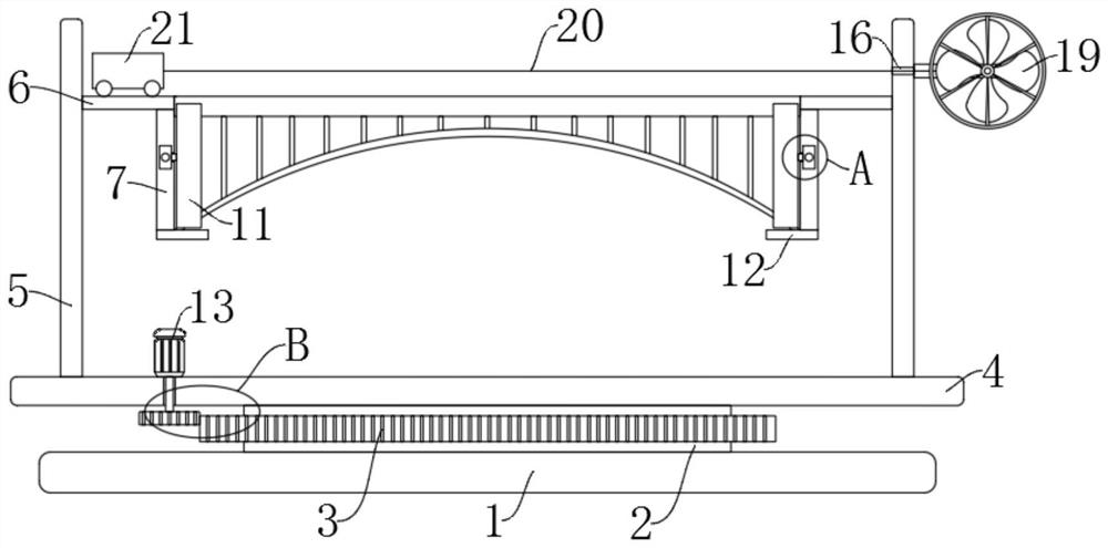
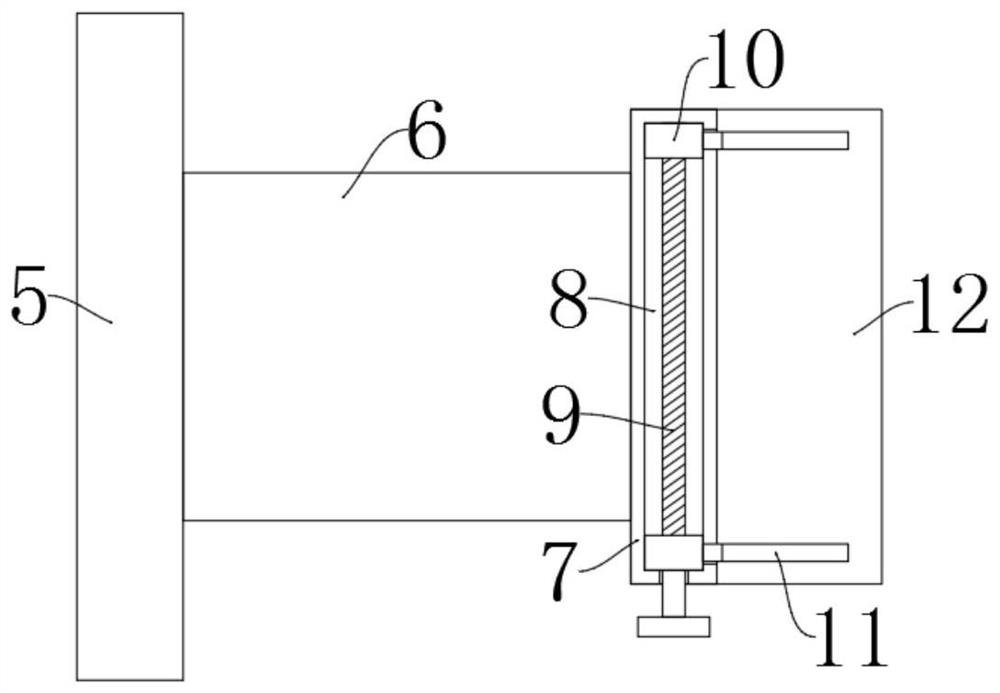
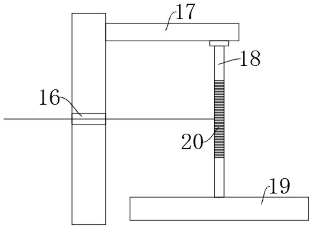
[0021] refer to Figure 1-6 , a bridge structure dynamics testing device, comprising a base 1, the upper side wall of the base 1 is fixedly connected with a connector 2, the upper end of the connector 2 is rotatably connected with a mounting table 4, and the side wall of the mounting table 4 is fixedly installed with a rotating mechanism, the rotation mechanism includes a drive motor 13 fixedly installed on the upper side wall of the installation platform 4, the end of the output shaft of the drive motor 13 is fixedly connected with a rotating shaft 14, and the end of the rotating shaft 14 runs through the side wall of the installation platform 4 and is fixedly connec...


PUM


Abstract

The invention discloses a bridge structure dynamics testing device, and relates to the technical field of testing. The bridge structure dynamics testing device comprises a base; the side wall of the upper end of the base is fixedly connected with a connecting piece; the upper end of the connecting piece is rotationally connected with a mounting table; a rotating mechanism is fixedly mounted on theside wall of the mounting table; two supports are fixedly connected to the side wall of the upper end of the mounting table. Through the use of a fixing mechanism, a bridge structure model is fixed on the device, and a driving motor is started to enable a rotating gear to rotate and drive the mounting table to rotate, so that a certain deflection angle is formed between the bridge structure modeland the air flow direction of a wind tunnel to monitor the vibration condition of the structure model in an oblique wind state; meanwhile, in order to enable the monitoring data to be more suitable for the actual situation, the vibration situation of the bridge structure model in the load state is monitored through position movement of a load trolley on the bridge structure model, and the situation that the deviation between the test data and the actual application situation is too large is avoided.

Description

technical field [0001] The invention relates to the technical field of testing, in particular to a bridge structure dynamic testing device. Background technique [0002] With the continuous increase of the span of modern bridges, bridges become softer and more sensitive to wind. The problem of wind resistance has become a key issue in the construction of long-span bridges. Wind resistance design and wind-induced response of bridge structures When checking the calculation, the aerodynamic parameters of the bridge are an important basis, so the accurate measurement of the static aerodynamic parameters is a very important link. Usually, the wind tunnel test equipment is used to measure the aerodynamic parameters of the bridge model, but most of the existing test equipment is fixed and cannot be used. At the same time, due to the limitation of the wind tunnel test conditions, the incoming wind cannot be adjusted. Therefore, when the existing test equipment is used to study the w...

Claims


Application Information

Patent Timeline
Patent Type & Authority Applications(China)
IPC IPC(8): G01M9/06G01M9/08G01M99/00
CPCG01M9/06G01M9/08G01M99/007
Inventor 李亚杰兰奇逊
Owner HENAN UNIV OF URBAN CONSTR
Why Eureka
Try Eureka