Supercharge Your Innovation With Domain-Expert AI Agents!

New energy automobile battery damping fixing box

A new energy vehicle and fixing box technology, which is applied to battery pack parts, circuits, vehicle maintenance, etc., can solve the problems of unfixable battery, loose fixation, battery damage, etc., and is conducive to safe use, avoiding collisions, The effect of improving stability

Inactive Publication Date: 2020-11-24
李晓艳
View PDF0 Cites 2 Cited by
  • Summary
  • Abstract
  • Description
  • Claims
  • Application Information

AI Technical Summary

Problems solved by technology

[0003] After the current new energy vehicle battery is installed into the installation box, the vehicle will bump when the new energy vehicle passes through a bumpy road, so that the fixed battery will also vibrate up and down, which will cause the battery and the top and bottom of the installation box. The battery is damaged due to the collision, and it is impossible to fix the battery while providing the corresponding cushioning and shock absorption function for the battery, which is not conducive to the safe use of the battery; at the same time, the traditional way of fixing the battery is to fix the battery directly through the fixing plate and screws. In the installation box, once the fixing plate is not tightly fixed to the battery and there is a gap, it is likely to cause the top of the battery to collide with the top of the installation box, and after the fixing plate is fixed and installed, it is impossible to see whether the fixing plate and the top of the battery are fixed Sufficient, thereby reducing the use effect of the new energy vehicle battery shock absorber fixing box

Method used


Image

  • New energy automobile battery damping fixing box
  • New energy automobile battery damping fixing box
  • New energy automobile battery damping fixing box

Examples


Embodiment 1

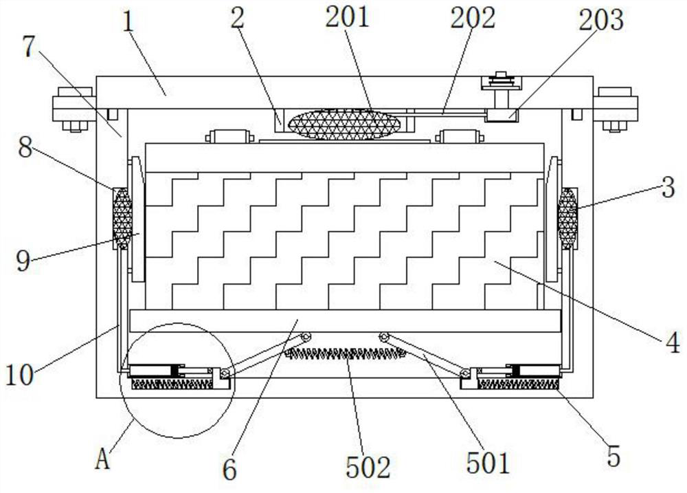
[0034] Example 1, such as Figure 1-7 As shown, when the battery 4 is installed inside the main body box 7, the battery 4 is manually put into the inside of the main body box 7, and the main body box 7 forces the movable plate 6 to descend due to gravity, so that the first connecting rod 501 and the second connecting rod 501 are connected to each other. The angle between the rod 142 and the bottom of the movable plate 6 becomes smaller gradually, the fourth spring 143 and the first spring 502 are stressed and stretched and store elastic potential energy, and the bottom end of the first connecting rod 501 pushes the first slide block 503 in the first slide. The inside of the groove 505 slides, the third spring 504 shortens and stores elastic potential energy, and the first connecting rod 501 pushes the cylinder 11 to shorten, forcing the pressure inside the cylinder 11 to increase, thereby forcing the second air bag 3 to expand a little more, thereby pushing the splint 9 Close ...

Embodiment 2

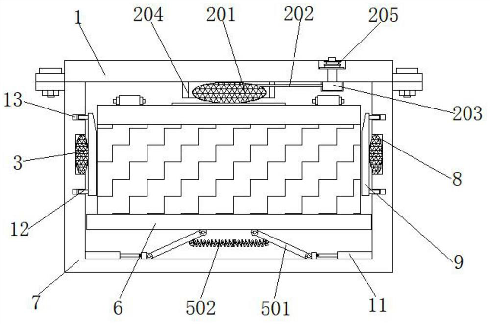
[0035] Example 2, such as figure 1 , 2 , 3, 4, 6 and 7, when the main body box 7 was stressed and bumped down, the angle between the second connecting rod 142 and the first connecting rod 501 and the bottom of the movable plate 6 continued to decrease, and the fourth spring 143 and the first A spring 502 is stressed and continues to stretch and store elastic potential energy. The bottom end of the first connecting rod 501 continues to push the first slider 503 to slide inside the first slide groove 505. The third spring 504 continues to shorten and store elastic potential energy. A connecting rod 501 pushes the cylinder 11 to shorten again, forcing the pressure inside the cylinder 11 to increase again, thereby forcing the second airbag 3 to expand even more, thereby pushing the splint 9 and the outside of the battery 4 to stick closer together, improving the device's resistance to the battery. The stability that storage battery 4 is fixed.

Embodiment 3

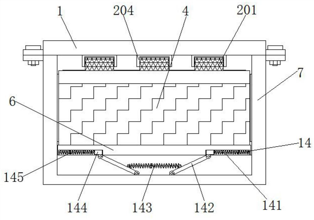
[0036] Example 3, such as Figure 1-7 As shown, when the main body box 7 is bumped up under force, the fourth spring 143, the first spring 502, the second spring 145 and the third spring 504 release the stored elastic potential energy, and the force generated by the elastic potential energy forces the movable plate 6 to drive the storage battery 4 rise together inside the main body box 7, and because the interior of multiple sets of first airbags 201 is filled with air, the first airbags 201 are deformed under force and buffer the received force.

[0037] Working principle: When it is necessary to install the battery 4 into the main body box 7, manually put the battery 4 into the main body box 7, and the main body box 7 will force the movable plate 6 to descend due to gravity, so that the first connecting rod 501 and the second connecting rod 501 The angle between the two connecting rods 142 and the bottom of the movable plate 6 becomes smaller gradually, the fourth spring 143...


PUM


Abstract

The invention discloses a new energy automobile battery damping fixing box. The new energy automobile battery damping fixing box comprises a main body; a cover plate is mounted at the top of the mainbox; a buffer assembly is arranged in the middle of the bottom of the cover plate; first damping assemblies are symmetrically arranged on the two sides of the inner bottom of the main box, a movable plate is arranged at the tops of the first damping assemblies jointly, second damping assemblies are symmetrically arranged at the two ends of the bottom of the movable plate, a storage battery is arranged at the top of the movable plate, and mounting grooves are symmetrically formed in the tops of the two ends in the main box. Through cooperative use of the cover plate, a second air bag, the storage battery, the first damping assemblies, the movable plate, the main box, the mounting grooves, a clamping plate, a second guide pipe, an air cylinder, an inserting rod, an inserting groove, a seconddamping assembly and a side plate; the storage battery fixing stability of the new energy automobile battery damping fixing box is improved, the storage battery is buffered and damped, the storage battery is prevented from colliding with the interior of the main box and being damaged, and safe use of the storage battery is facilitated.

Description

technical field [0001] The invention relates to the technical field of new energy vehicles, in particular to a shock absorbing and fixing box for batteries of new energy vehicles. Background technique [0002] When a new energy vehicle is running, the internal battery of the car will vibrate due to the inertial force generated by the running of the car, and the battery will bump when the car is bumping. Due to the chemicals inside the battery, continuous violent bumping will make its internal disorder, and then The car battery needs to be fixed. [0003] After the current new energy vehicle battery is installed into the installation box, the vehicle will bump when the new energy vehicle passes through a bumpy road, so that the fixed battery will also vibrate up and down, which will cause the battery and the top and bottom of the installation box. The battery is damaged due to the collision, and it is impossible to fix the battery while providing the corresponding cushioning...

Claims


Application Information

Patent Timeline
IPC IPC(8): H01M2/10B60K1/04B60S5/06
CPCB60K1/04B60S5/06
Inventor 李晓艳
Owner 李晓艳
Features
  • R&D
  • Intellectual Property
  • Life Sciences
  • Materials
  • Tech Scout
  • Unparalleled Data Quality
  • Higher Quality Content
  • 60% Fewer Hallucinations
Learn More