stereo camera setup
A technology of a stereo camera and an image processing device, which is applied to a measuring device, a stereo system, and an optical device, etc., can solve the problem that the correction of parallax shift cannot be fully ensured, and achieve the effect of reducing the calculation cost.
- Summary
- Abstract
- Description
- Claims
- Application Information
AI Technical Summary
Problems solved by technology
Method used
Image

Examples
no. 1 Embodiment approach >
[0036] side reference Figure 1 to Figure 14 , the first embodiment of the present invention will be described.
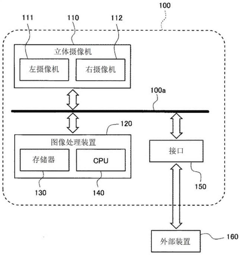
[0037] figure 1 It is a figure which shows the hardware structure of the stereo camera apparatus of this embodiment.
[0038] figure 1 Among them, the stereo camera device 100 includes: a stereo camera 110 (camera device) including a pair of left and right cameras (image pickup units) of a left camera 111 and a right camera 112; and an image processing device 120 including a read-only memory ( A memory 130 such as a ROM) or a random access memory (RAM) and a central processing unit (CPU) 140 as a processor; and an interface 150 for communicating between the stereo camera device 100 and the outside through CAN (Control Area Network) communication or the like Communication between external devices 160 such as sensors and other devices is performed, and the stereo camera 110 , the image processing device 120 , and the interface 150 are connected by a bus line 100 a...
no. 2 Embodiment approach >
[0101] side reference Figure 15 and Figure 16 , the second embodiment of the present invention will be described. In this embodiment, only differences from the first embodiment will be described, and in the drawings used in this embodiment, the same reference numerals are given to the same members as those of the first embodiment, and descriptions will be omitted.
[0102] This embodiment shows the case where the parallax shift correction amount calculation determination unit 610 is provided, which determines whether or not to perform parallax shift based on whether or not the parallax shift correction amount can be calculated with high accuracy. Calculation of the correction amount (parallax shift correction amount calculation processing). In the present embodiment, in order to obtain the parallax shift correction amount with high accuracy, it is important to satisfy the following two conditions: The movement amount of the own vehicle, which is a parameter for calculating...
no. 3 Embodiment approach >
[0118] side reference Figure 18 , the third embodiment of the present invention will be described. In this embodiment, only differences from the second embodiment will be described, and in the drawings used in this embodiment, the same reference numerals are given to the same members as those of the second embodiment, and descriptions thereof will be omitted.
[0119] In the present embodiment, a parallax shift correction amount calculation determination unit 610A that determines the execution of the parallax shift correction amount calculation process is provided instead of the parallax shift correction unit 121A provided in the second embodiment, which determines that the parallax shift correction is not to be performed. The parallax offset correction amount calculation determination unit 610 in the case of the amount calculation process. That is, in the present embodiment, when the parallax shift correction amount calculation determination unit 610A determines that the pa...
PUM
 Abstract
Description
Claims
Application Information
 - R&D
- Intellectual Property
- Life Sciences
- Materials
- Tech Scout
- Unparalleled Data Quality
- Higher Quality Content
- 60% Fewer Hallucinations
Browse by: Latest US Patents, China's latest patents, Technical Efficacy Thesaurus, Application Domain, Technology Topic, Popular Technical Reports.
© 2025 PatSnap. All rights reserved.Legal|Privacy policy|Modern Slavery Act Transparency Statement|Sitemap|About US| Contact US: help@patsnap.com