Novel fire extinguishing pipeline system

A fire extinguishing pipe, a new type of technology, applied in fire rescue and other directions, can solve the problems of pressure loss, small flow, uneven flow distribution and other problems along the way, and achieve the effect of reducing energy loss, reducing pressure loss, and reducing energy loss

Pending Publication Date: 2020-11-27
SICHUAN UNIVERSITY OF SCIENCE AND ENGINEERING +1
View PDF0 Cites 1 Cited by
  • Summary
  • Abstract
  • Description
  • Claims
  • Application Information

AI Technical Summary

Problems solved by technology

[0005] The technical problem to be solved by the present invention is to provide a new type of fire extinguishing pipeline system to improve the problem of serious pressure loss along the way in the existing diversion structure, resulting in small flow and uneven flow distribution

Method used


Image

  • Novel fire extinguishing pipeline system
  • Novel fire extinguishing pipeline system
  • Novel fire extinguishing pipeline system

Examples


Embodiment

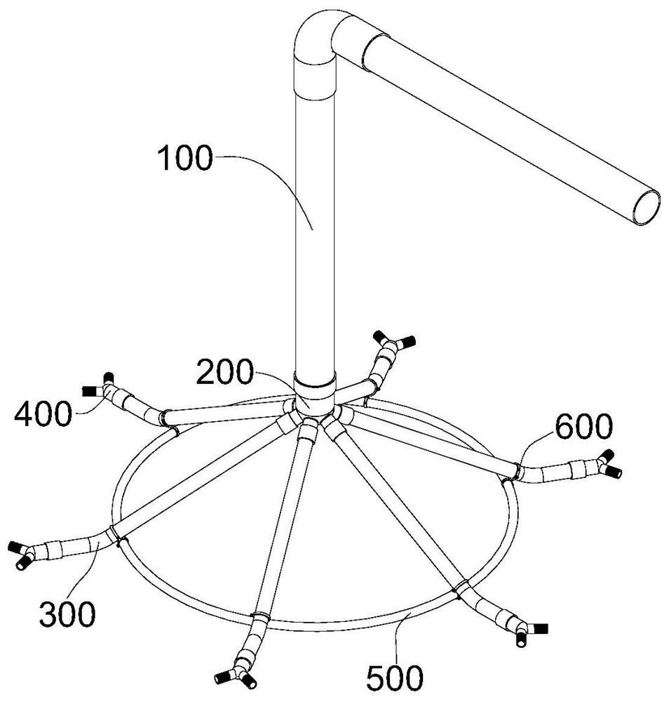
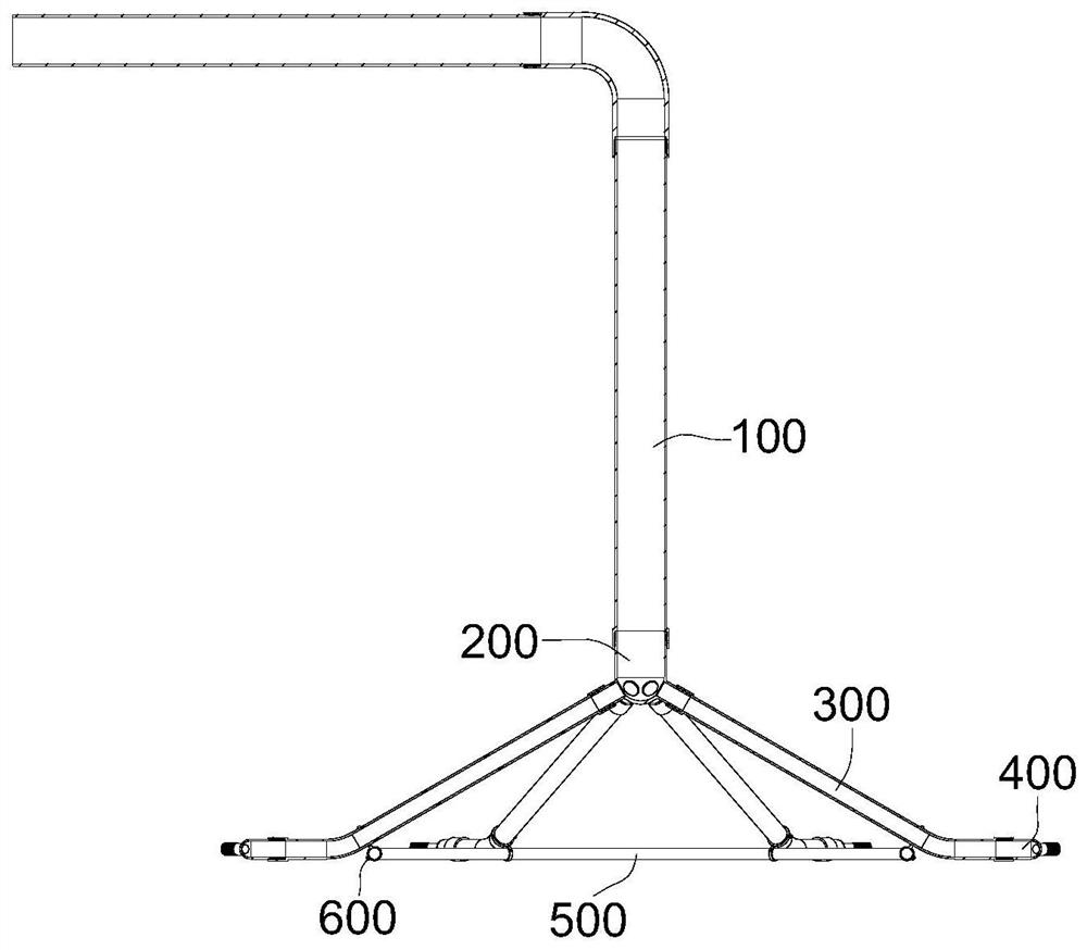
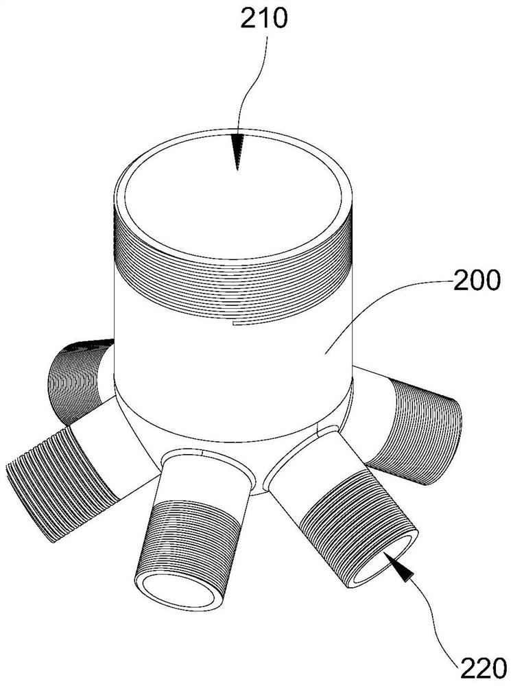
[0026] like Figure 1 to Figure 12 As shown, the embodiment of the present invention discloses a novel fire extinguishing pipeline system, which includes a main pipeline and at least two auxiliary pipelines. The main pipeline includes a main pipeline 100 and a spherical branch fluid 200, and the spherical branch fluid 200 includes a cavity A body 230, a first flow channel 210 and at least two second flow channels 220, the main flow pipe 100 communicates with the first flow channel 210, the first flow channel 210 and the at least two second flow channels 220 are both connected to The cavity 230 is in communication, at least two of the second flow channels 220 are evenly distributed along the circumferential direction of the spherical shunt 200, and the second flow channels 220 and the first flow channel 210 are arranged obliquely; the The auxiliary pipeline includes a connecting pipe 300 and a joint 400. One end of the connecting pipe 300 is connected to the spherical shunt 200...


PUM


Abstract

The invention discloses a novel fire extinguishing pipeline system. The novel fire extinguishing pipeline system comprises a main pipeline and at least two auxiliary pipelines, wherein the main pipeline comprises a main flow pipe and a spherical flow dividing body; the spherical flow dividing body comprises a cavity, a first runner and at least two second runners; the main flow pipe communicates with the first runner; the first runner and the at least two second runners communicate with the cavity; the at least two second runners are evenly distributed in the circumferential direction of the spherical flow dividing body, and the second runners and the first runner are obliquely arranged; and each auxiliary pipeline comprises a connecting pipe and a connector, wherein one end of the connecting pipe is connected with the spherical flow dividing body, the at least two connecting pipes and the at least two second runners are arranged in a one-to-one correspondence manner, and the connectoris arranged at the end, deviating from the spherical flow dividing body, of the connecting pipe. According to the novel fire extinguishing pipeline system disclosed in the embodiment, the spherical flow dividing body is adopted for flow dividing, the second runners on the spherical flow dividing body are distributed in a completely symmetric manner, the pressure drop is consistent, and the purpose of uniform outflow is achieved.

Description

technical field [0001] The invention relates to the technical field of fire fighting equipment, in particular to a novel fire extinguishing pipeline system. Background technique [0002] In large-scale fires, the design of the fire extinguishing pipe network system is very important. The distribution parts and nozzles are the key components of the entire fire extinguishing pipe network system, and the rationality of their structure is closely related to the fire extinguishing performance of the entire system. [0003] In actual life, the phase state of many fire extinguishing media is easily affected by temperature and pressure. For example, the liquid CO2 stored in the tank after pressurized liquefaction, due to the sudden drop of pipeline pressure when the valve is opened, in Joule- Under the Thomson effect, the liquid CO2 flashes instantaneously, and the CO2 flash expansion and phase change endothermic will cause the temperature of the conveying pipeline to drop sharply, ...

Claims


Application Information

Patent Timeline
IPC IPC(8): A62C31/03A62C31/28
CPCA62C31/03A62C31/28
Inventor 胡光忠刘娜卢涛汪映标胡安林
Owner SICHUAN UNIVERSITY OF SCIENCE AND ENGINEERING
Why Eureka
Try Eureka