Heat dissipation device applied to numerical control laser cutting

A technology of heat dissipation device and numerical control laser, applied in numerical control field, can solve the problem of poor heat dissipation effect, etc., and achieve the effect of improving heat dissipation effect

Inactive Publication Date: 2020-11-27
宣城顺心信息技术服务有限公司
View PDF0 Cites 5 Cited by
  • Summary
  • Abstract
  • Description
  • Claims
  • Application Information

AI Technical Summary

Problems solved by technology

[0004] Based on the technical problem of poor heat dissipation effect on the laser cutting position of the workpiece in the prior art, the present invention proposes a heat dissipation device applied to CNC laser cutting

Method used


Image

  • Heat dissipation device applied to numerical control laser cutting
  • Heat dissipation device applied to numerical control laser cutting
  • Heat dissipation device applied to numerical control laser cutting

Examples


Embodiment 1

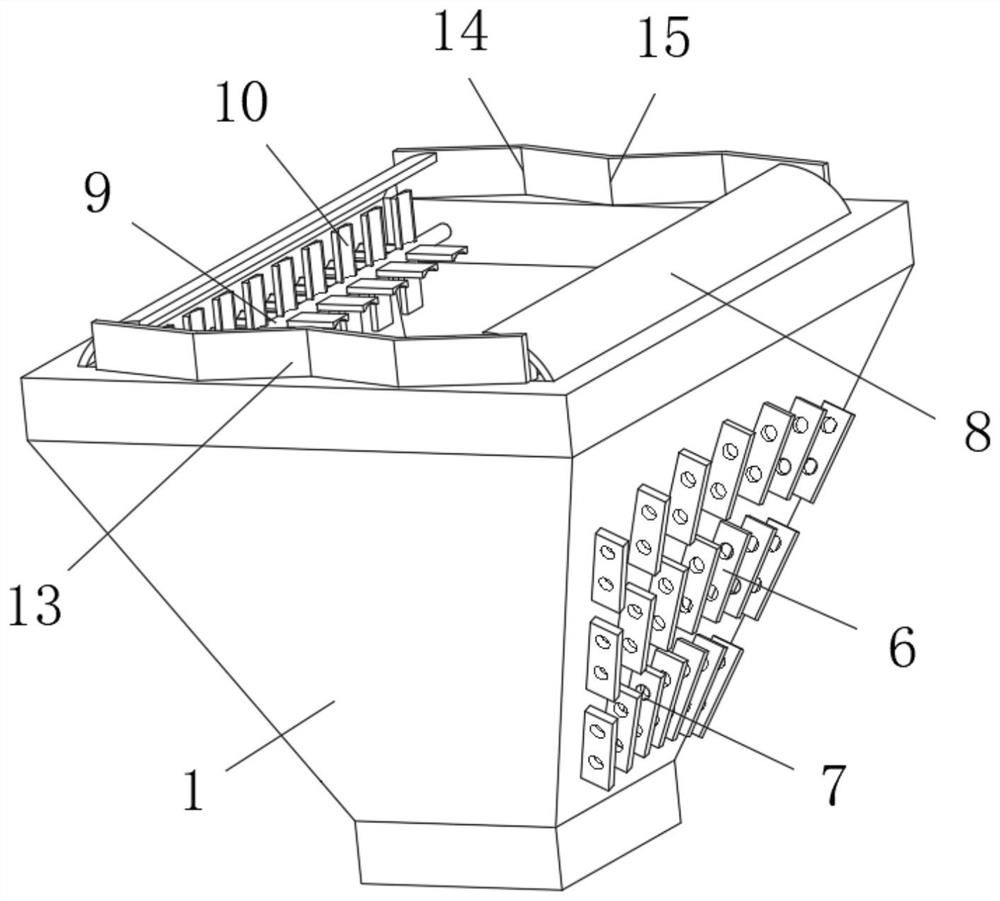
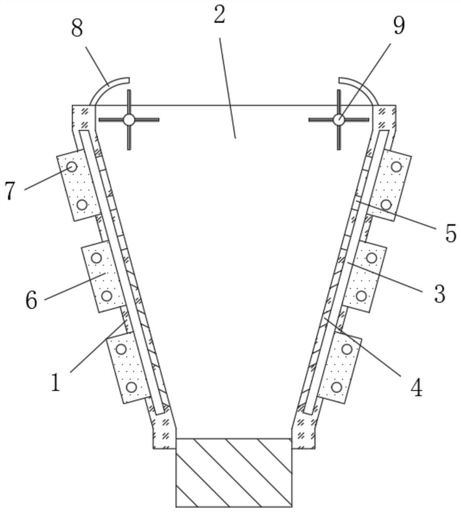
[0027] refer to Figure 1-4 , a heat dissipation device applied to CNC laser cutting, including a hopper 1, a collection chamber 2 is arranged inside the hopper 1, and the cross-sectional area of ​​the collection chamber 2 decreases gradually as the height decreases, and the bottom end of the collection chamber 2 is connected with The exhaust pipe, the two ends of the hopper 1 and the inner walls on both sides are all set as inclined surfaces, and the inside of the shell on both sides of the hopper 1 is provided with a connecting cavity 3, and the connecting cavity 3 is provided with an inclined shape that matches the inner wall of the collecting cavity 2. The top of the inner wall of the connection chamber 3 close to the collection chamber 2 is provided with a plurality of ventilation holes 5, and the bottom of the inner wall of the connection chamber 3 near the collection chamber 2 is provided with a plurality of ventilation holes 4, and the connection chamber 3 is far away f...

Embodiment 2

[0035] refer to Figure 1-5, a heat dissipation device applied to CNC laser cutting, the inner walls of both ends of the hopper 1 are provided with auxiliary grooves 16 distributed equidistantly in the vertical direction, and the auxiliary grooves 16 are arranged in a V-shaped structure, and the middle position of the auxiliary grooves 16 Protruding upward, a diffuser groove 17 with an arc-shaped structure is opened in the middle of the bottom inner wall of the auxiliary groove 16 .

[0036] When in use, the middle position of the auxiliary groove 16 protrudes upwards, so that the hot air entering the auxiliary groove 16 on both sides is led to the middle position and dispersed through the diffusion groove 17 to reduce the upward impact force, and the hot air entering the auxiliary groove 16 at the middle position will flow along the The auxiliary groove 16 drains water to the bottom of both sides, so as to further enhance the actual heat dissipation effect of the device on CN...


PUM


Abstract

The invention belongs to the technical field of numerical control, particularly relates to a heat dissipation device applied to numerical control laser cutting, and aims to solve the problem of a poorheat dissipation effect on the laser cutting position of a workpiece in the prior art. The heat dissipation device comprises a hopper; a collecting cavity is arranged inside the hopper, and the areaof the cross section of the collecting cavity is gradually reduced along with the height reduction; the bottom end of the collecting cavity is connected with an air exhaust pipe; the two ends of the hopper and the inner walls of the two sides of the hopper are all inclined surfaces; and connecting cavities are formed in a shell and on the two sides of the hopper, and the connecting cavities are inan inclined shape matched with the inner walls of the collecting cavity. According to the heat dissipation device, hot gas overflowing from the top to the side of the collecting cavity is sucked intothe connecting cavity from an air exhaust hole to be used for pre-heat dissipation and temperature reduction through radiating fins, and then descends and is led out from a vent hole instead of reversely overflowing from the side, and thus the actual heat dissipation effect on the numerical control laser cutting position of the workpiece is improved.

Description

technical field [0001] The invention relates to the technical field of numerical control, in particular to a heat dissipation device applied to numerical control laser cutting. Background technique [0002] Numerical control is the abbreviation of numerical control. Numerical control technology is a method to control mechanical movement and processing process by using digital information. The machining of numerical control system has the characteristics of high precision. With the continuous development of numerical control technology, the application of numerical control system has been deeply In all aspects of machining, CNC laser cutting is part of the application of CNC systems. [0003] CNC laser cutting is to use high-energy-density laser beams to heat the workpiece through numerical control, so that the temperature rises rapidly and reaches the boiling point of the material in a very short time. While the steam is ejected, an incision is formed on the material. Durin...

Claims


Application Information

Patent Timeline
Patent Type & Authority Applications(China)
IPC IPC(8): B23K26/38B23K26/70
CPCB23K26/38B23K26/703
Inventor 史淑芬
Owner 宣城顺心信息技术服务有限公司
Why Eureka
Try Eureka