Automatic powder feeding tool for ceramic-lined pipe line

A ceramic lining and pipeline technology, which is applied in the field of automatic powder feeding equipment for ceramic lining pipes, can solve problems such as poor precision, powder dust pollution, and poor working environment for workers, and achieve convenient use and good results

Pending Publication Date: 2020-11-27
LINYI WAGON NEW MATERIAL TECH LTD
View PDF0 Cites 0 Cited by
  • Summary
  • Abstract
  • Description
  • Claims
  • Application Information

AI Technical Summary

Problems solved by technology

[0004] First of all, the basic structure of the ceramic lined pipeline is as attached to the instruction manual. figure 1 Shown: When preparing a ceramic lined pipe, it is necessary to supply powder into the pipe. In the early stage of the experiment, a round pipe was cut in half, and then the opening was f

Method used


Image

  • Automatic powder feeding tool for ceramic-lined pipe line
  • Automatic powder feeding tool for ceramic-lined pipe line
  • Automatic powder feeding tool for ceramic-lined pipe line

Examples


Embodiment 1

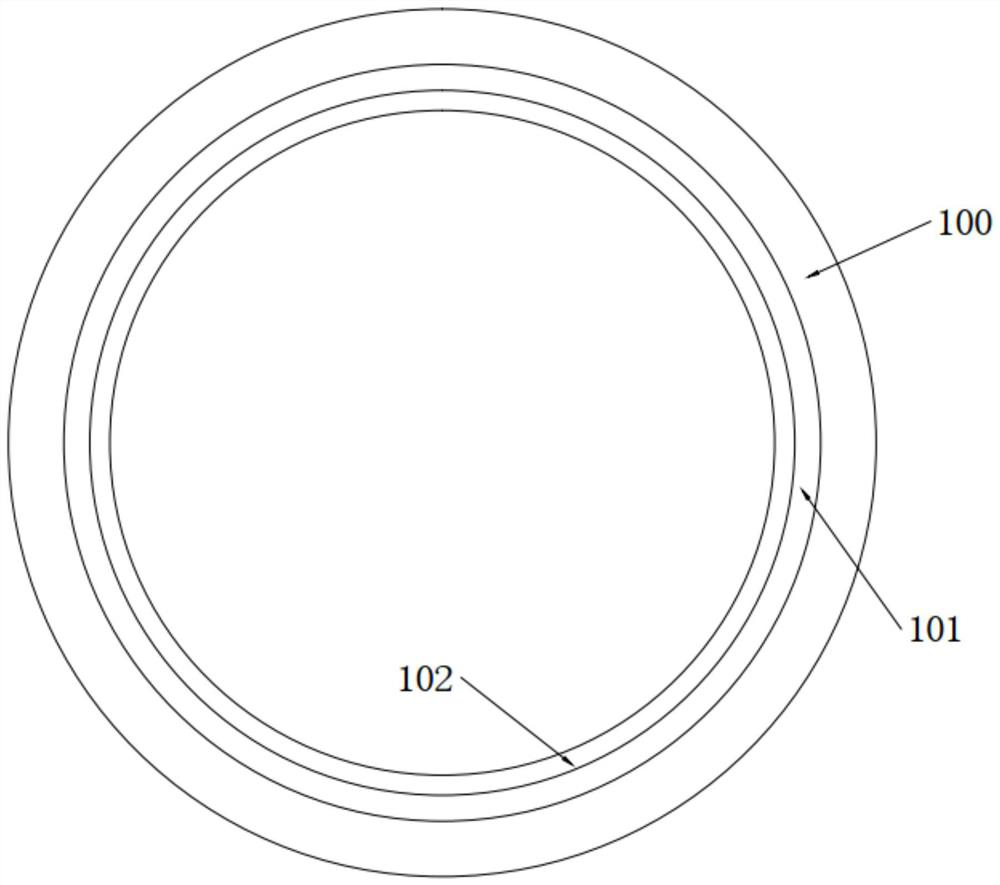
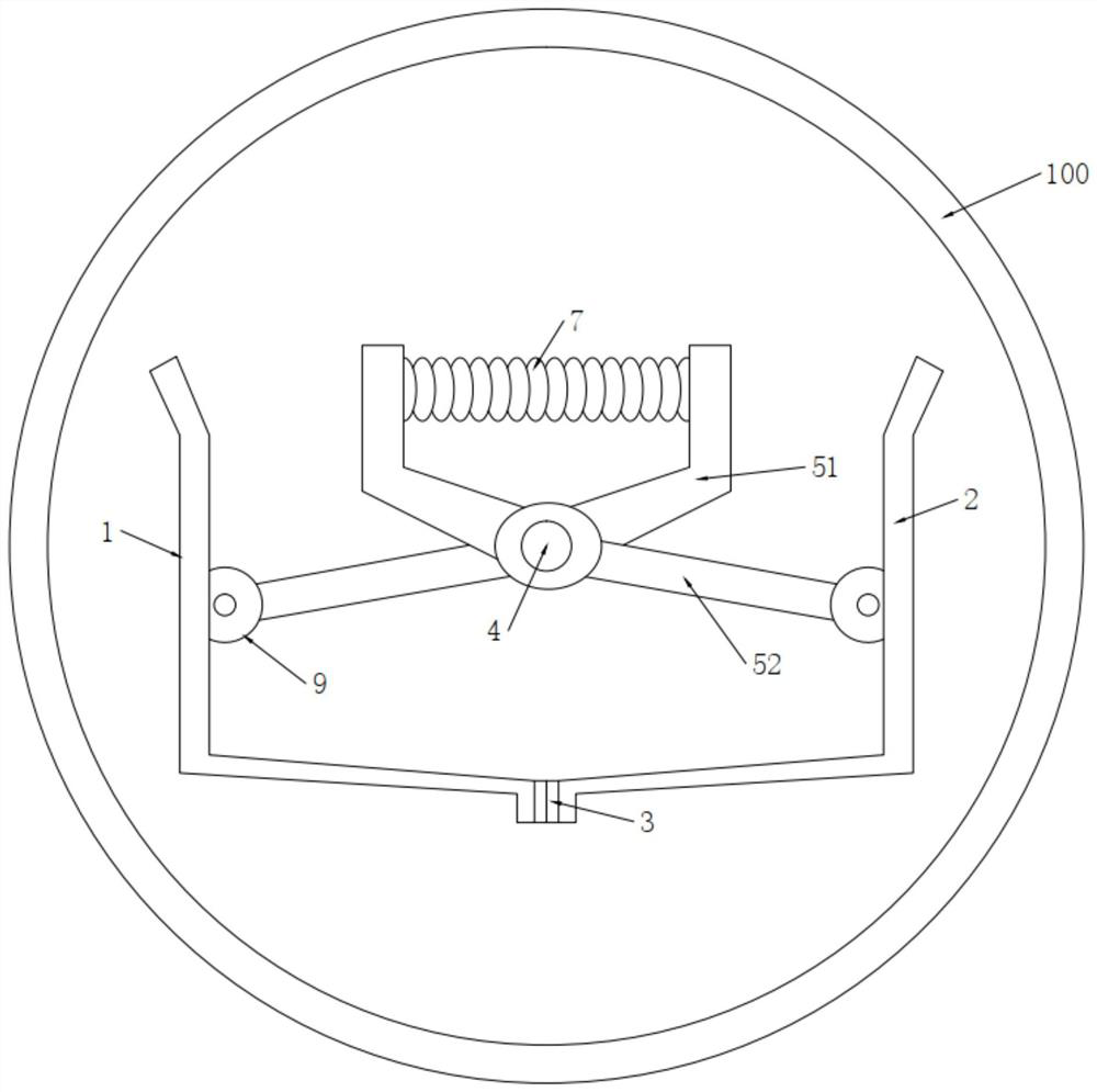
[0029] Embodiment 1: An automatic powder feeding tool for ceramic lined pipes, including symmetrically arranged strip-shaped left L-shaped sheet metal parts 1 and right L-shaped sheet metal parts 2, two long strip-shaped left The L-shaped sheet metal part 1 and the right L-shaped sheet metal part 2 can be set to be consistent with the length of the carbon steel pipe 100 to be coated, and the left L-shaped sheet metal part 1 and the right L-shaped sheet metal part 2 can be selected Similar to angle steel sheet metal parts, two L-shaped sheet metal parts are close to each other to form a groove-like structure, and a flat end surface is formed at the bottom for powder loading. The left L-shaped sheet metal part 1 and the right L-shaped L-shaped sheet metal part 2 can be separated, that is, the left L-shaped sheet metal part 1 and the right L-shaped When the joints of the L-shaped sheet metal parts 2 are separated from each other, the bottom can be opened to realize the function o...

Embodiment 2

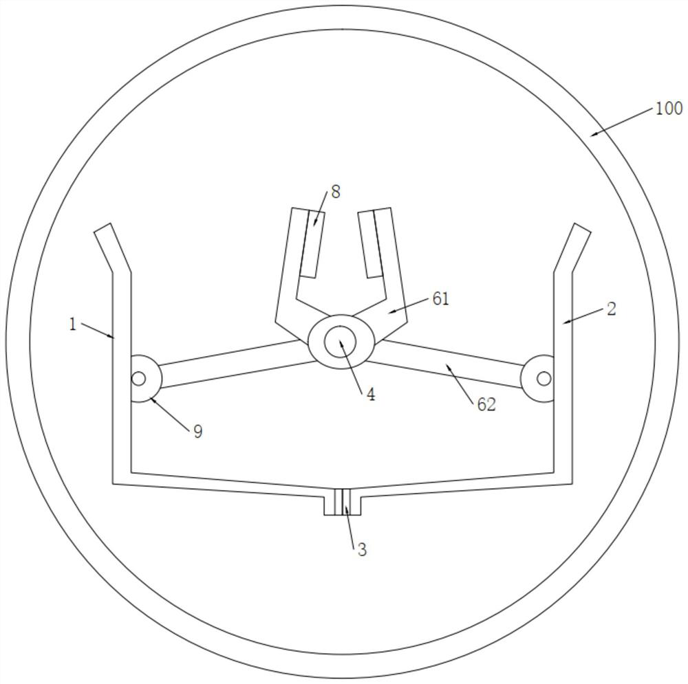
[0034] The difference from Embodiment 1 of the present application is that, as shown in the description attached Figure 5-7 As shown, a connection spring 7 is fixedly connected between the two normally closed vise heads 51, and an electromagnet 8 is fixedly connected to one end of the two opening and closing vise heads 61 that are close to each other. The connection spring 7 in the stretched state is fixedly connected, and the two electromagnets 8 are energized to repel each other away from each other. As attached to the manual Figure 5 As shown, the connection spring 7 is in an extended state, and the connection spring 7 will provide a force to pull the normally closed vise head 51 inward, thereby pulling the normally closed vise handle 52 inward, and driving the sheet metal on the left and right sides The lower end of the part is squeezed inward, so that the gasket 3 at the bottom of the sheet metal part is squeezed by the reaction force, so that the bottoms of the two L-...


PUM


Abstract

The invention discloses an automatic powder feeding tool for a ceramic-lined pipe line. The tool comprises a left L-shaped sheet metal part and a right L-shaped sheet metal part that are symmetricallyarranged in a long strip shape, wherein an opening and closing vise mechanism is provided on a vise shaft, an opening and closing vise comprises opening and closing vise heads and an opening and closing vise handle, a connecting spring is fixedly connected between the two normally closed vise heads, and the close ends of the two opening and closing vise heads are fixedly connected with electromagnets. Through the arrangement of a connecting spring and the electromagnets in the invention and matching the use of the vise structure, the contact position between the bottoms of the two sheet metalparts can be opened and closed as long as the electromagnet is energized and de-energized; when the bottom is closed, powder is added to the groove formed by the sheet metal parts; and when the bottom is open, the powder is poured from the bottom to add powder to the pipe. The tooling is matched with a transmission device to achieve subsequent automatic feeding after going deep into the pipe, which is very convenient to use and has a good effect.

Description

technical field [0001] The invention relates to the technical field of production of ceramic lined pipes, in particular to an automatic powder feeding tool for ceramic lined pipes. Background technique [0002] Anti-corrosion pipes include: alloy, glass-lined pipes, Teflon-lined pipes, tempered glass pipes, etc.; the current alloy-ceramic composite pipes are made by themselves, and there are still problems in efficiency. [0003] The specific problem is this: [0004] First of all, the basic structure of the ceramic lined pipeline is as attached to the instruction manual. figure 1 Shown: When preparing a ceramic lined pipe, it is necessary to supply powder into the pipe. In the early stage of the experiment, a round pipe was cut in half, and then the opening was filled with powder upwards. When the half pipe was put into the round pipe to be sintered When pipe, the half pipe is dumped 180 degrees, and the powder is poured into the pipe. There are several problems here. One...

Claims


Application Information

Patent Timeline
IPC IPC(8): B28B19/00B28B13/02
CPCB28B13/02B28B19/0023
Inventor 贾瓦德刘海波
Owner LINYI WAGON NEW MATERIAL TECH LTD
Why Eureka
Try Eureka