Valve block of electronic throttle valve, electronic throttle valve and valve block assembling method

An electronic throttle valve and assembly method technology, applied in the direction of engine control, machine/engine, mechanical equipment, etc., can solve the problem of cumbersome tooling replacement, simplify the assembly process, avoid sharp edges and corners, and prevent valve plates from scratching gas Tao effect

Pending Publication Date: 2020-11-27
ZHEJIANG KEBODA IND
View PDF0 Cites 0 Cited by
  • Summary
  • Abstract
  • Description
  • Claims
  • Application Information

AI Technical Summary

Problems solved by technology

Therefore, in order to ensure that the positions of the bolts of the two electronic throttle valves are consistent, the installation form of the positioning tool needs to be replaced when switching between the two electronic throttle valves during the production process, and the position of the fixture also needs to be adjusted to ensure that the product is installed on the tooling After turning the valve plate to the corresponding bottom dead center position, the valve plate is in the horizontal direction, the ejector rod of the tooling can play a supporting role on the valve plate, and the position of the electric torque gun does not need to be changed, but this will lead to Tooling replacement is more cumbersome

Method used


Image

  • Valve block of electronic throttle valve, electronic throttle valve and valve block assembling method
  • Valve block of electronic throttle valve, electronic throttle valve and valve block assembling method
  • Valve block of electronic throttle valve, electronic throttle valve and valve block assembling method

Examples


Embodiment Construction

[0039] The present invention will be described in detail below in conjunction with the accompanying drawings and specific embodiments.

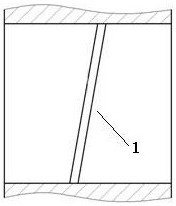
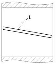
[0040] Figure 9 with Figure 10 The structure of the existing electronic throttle plate is shown. Such as Figure 9 with Figure 10As shown, the side of the valve plate 1 of the existing electronic throttle is formed by a slope 10 . Moreover, the installation directions of the electronic throttle valve plates of gasoline engines and diesel engines are also different.

[0041] Figure 11 with Figure 12 The structure of the valve plate of the electronic throttle according to the first embodiment of the present invention is shown. The outer surface of the valve plate 1a according to the first embodiment of the present invention is composed of a first slope 11 and a second slope 12, the first slope 11 and the second slope 12 are inclined toward one side of the valve plate, and are symmetrical to each other, forming a V Shape symmetrical...


PUM


Abstract

The invention discloses a valve block of an electronic throttle valve, the electronic throttle valve and a valve block assembling method. The outer side face of the valve block of the electronic throttle valve is composed of a first inclined face and a second inclined face, and the first inclined face and the second inclined face both incline towards one side of the valve block and are symmetric to each other. The bottom end of the first inclined face and the bottom end of the second inclined face intersect. In the assembling process of the valve block, the mounting direction of the valve block does not need to be recognized, a tool does not need to be adjusted or replaced during type changing and assembling of a gasoline engine electronic throttle valve and a diesel engine electronic throttle valve adopting the valve block, and therefore assembling is convenient.

Description

technical field [0001] The invention relates to an electronic throttle technology of an automobile engine intake system. Background technique [0002] In the engine intake system, the electronic throttle adjusts the engine speed and output power by controlling the amount of intake air supplied to the intake manifold. The electronic throttle adjusts the flow area of ​​air passing through the air passage by controlling the position of the valve plate, and then adjusts the intake air volume. There are two limit positions in the adjustable range of the valve plate 1, which are called the dead center position, and the position where the theoretical flow area is zero is called the bottom dead center position, such as figure 1 shown; top dead center position as figure 2 As shown, it is one of the positions in the range of positions where the theoretical flow area is the largest. [0003] At present, the electronic throttle can be used on two platforms of gasoline engine and die...

Claims


Application Information

Patent Timeline
Patent Type & Authority Applications(China)
IPC IPC(8): F02D9/10
CPCF02D9/10F02D9/107
Inventor 廖彦文梁世颇张时来朱跃伟肖永涛
Owner ZHEJIANG KEBODA IND
Why Eureka
Try Eureka